


15.
Assembly and adjustments
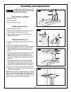
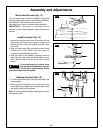
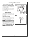
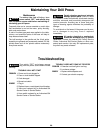
To square the table to the head (Fig. 20)
1. Insert a 3" (7.6 cm) drill bit (1) into the chuck (2) and
tighten.
2. Raise and lock the table (3) about 1" (2.5 cm) from
the end of the drill bit.
3. Place a combination square (4) on the table as
shown. The drill bit should be parallel to the straight
edge of the square.
4. If an adjustment is needed, loosen the bevel lock (5)
with a wrench.
5. Square the table to the bit by tilting the table.
6. Tighten the bevel lock bolt (5) when square.
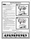
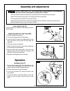
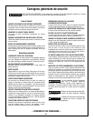
Drilling depth (Fig. 21)
1. To stop the drill at a specific depth for consistent and
repetitive drilling, loosen the depth scale lock (1)
located on the depth scale hub (2).
2. Turn the hub until the pointer (3) is aligned to the
desired depth on the scale.
3. Tighten the depth scale lock (1). the chuck will stop
after traveling downward to the distance selected.
Note: All the necessary adjustments for the working of
your drill press have been done at the factory. Please
do not modify them. However, because of normal wear
and tear of your tool, some readjustments might be
necessary.
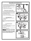
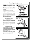
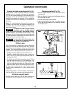
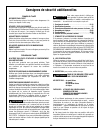
Spindle return spring (Fig. 22)
The spindle is equipped with an auto-return mechanism.
The main components are a spring and a notched
housing. The spring was properly adjusted at the factory
and should not be readjusted unless absolutely
necessary. If it needs to be adjusted, proceed as
follows:
1. Unplug the drill press.
2. Place a screwdriver into the loop
(1) to hold the
spring in place.
3. Loosen the two housing nuts (2) approximately 1/4"
(6 mm). Do not remove the nuts from the threaded
shaft.
4. While firmly holding the spring housing (3), carefully
pull it out until it clears the raised notch (4). Turn it until
the next notch (5) is engaged with the raised notch (to
increase the tension, turn it counterclockwise; to
decrease the tension, turn it clockwise). Tighten the two
housing nuts.
IMPORTANT! Do not overtighten the two nuts. If the
nuts are tightened too much, the movement of the
spindle and feed handles will be sluggish.
FIG. 20
2
3
1
5
4
FIG. 21
1
3
2
F
FIG. 22
5
1
2
3
4