


10
.
Assembly and adjustments
Disconnect the plug from the power
source before making any assembly,
adjustments or changing accessories.
Such preven-
t
ive safety measures reduce the risk of starting the tool
a
ccidentally.
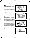
Assembly instructions
No assembly required. Prior to making adjustments you
may want to mount the scroll saw on a stable surface.
See Bench mounting the saw.
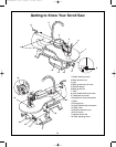
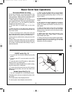
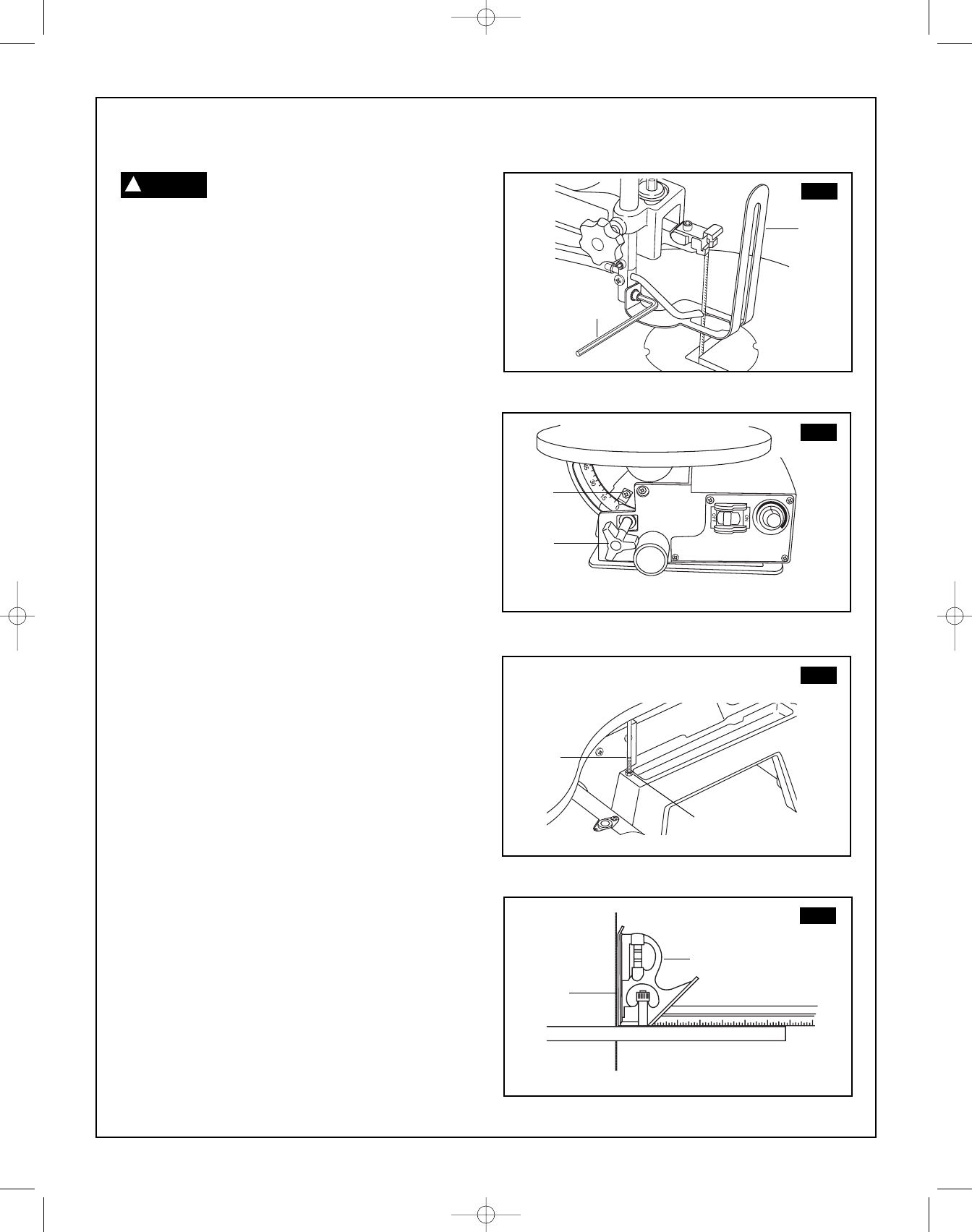
Align the bevel indicator (Fig. 3–6)
The bevel indicator has been factory adjusted. It should
be rechecked prior to use for best operation.
1. Remove the blade guard foot
(1) using the hex key (2)
to loosen the screw.
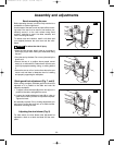
2. Loosen the table bevel lock knob
(3) and move the
table until it is approximately at a right angle to the
blade.
3. Loosen the locking nut (5) on the table adjusting screw
(6) under the table by turning it counterclockwise.
Lower the table adjusting screw by turning it clock-
wise.
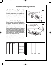
4. Use a combination square (7) to set the table exactly
90° to the blade (8). If there is space between the
square and blade, adjust the table angle until the
space is closed.
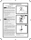
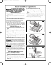
5.
Lock the table bevel lock knob under the table
(3) to
prevent movement.
6. Tighten the adjusting screw under the table until the
tip of the screw touches the table. Tighten the lock nut.
7. Loosen the screw (4) holding the bevel scale pointer
and position pointer to 0°. Tighten the screw.
8. Attach the blade guard foot (1) using the hex key (2),
so that the foot rests flat against the table. Tighten the
screw.
Note: Avoid setting the edge of the table against the top
of the motor, which could cause noise when the saw is
running.
FIG. 3
2
FIG. 4
1
2
FIG. 5
FIG. 6
1
4
3
6
5
7
8
WARNING
!
SM 2610957121 05-08 6/5/08 7:35 AM Page 10