


Basic Scroll Saw Operations
To avoid injury from accidental start-
ups, always turn the switch OFF and
unplug the scroll saw before moving the tool,
replacing the blade, or making adjustments.
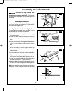
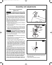
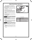
Interior cutting (Fig. 17)
1. Lay out the design on the workpiece. Drill a 1/4" hole
i
n the workpiece.
2. Remove the blade. See Blade removal and installa-
tion.
3. Place the workpiece on the saw table with the hole in
the workpiece over the access hole in the table.
4. Install a blade through the hole in the workpiece.
5. Follow steps 3-7, under Freehand cutting.
6. When finished making the interior scroll cuts simply
turn the scroll saw OFF. Unplug the saw before
removing the blade from the blade holder. Remove
the workpiece from the table.
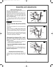
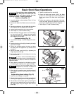
Freehand cutting (Fig. 18)
1. Lay out desired design, or secure design to the work-
piece.
2. Raise the blade guard foot
(1) by loosening the height
adjustment knob (2).
3. Position the workpiece against the blade and place
the blade guard foot against the top surface of the
workpiece.
4. Secure the blade guard foot (1) by tightening the
height adjustment knob (2).
5. Remove the workpiece from the blade prior to turning
the scroll saw ON.
In order to avoid uncontrollable lifting of
the workpiece and to reduce blade break-
age, do not turn the switch on while the workpiece is
against the blade.
6. Slowly feed the workpiece into the blade by guiding
and pressing the workpiece down against the table.
Do not force the leading edge of the
workpiece into the blade. The blade will
deflect, reducing accuracy of cut, and may break.
7. When the cut is complete, move the trailing edge of
the workpiece beyond the blade guard foot. Turn the
switch OFF.
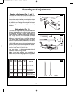
Angle cutting (bevel cutting) (Fig. 19)
1. Layout or secure design to workpiece.
2. Move the blade guard foot to the highest position by
loosening the height adjustment knob
(3). Retighten.
3. Tilt the table to the desired angle by loosening the
table bevel lock handle
(4) and moving the table to
the proper angle using the degree scale and the
pointer
(5).
4. Tighten the table bevel lock handle (4).
5. Loosen the blade guard screw, and tilt the blade
guard to the same angle as the table. Retighten the
blade guard screw. See Hold down clamp adjust-
ment'.
6. Position the workpiece on the right side of the blade.
Lower the blade guard foot against the surface by
loosening the height adjustment knob. Retighten.
7. Follow steps 5–7 under Freehand cutting.
2
FIG. 18
1
45
30
15
3
FIG. 19
4
5
FIG. 17
WARNING
!
CAUTION
!
CAUTION
!
15.
SM 2610957121 05-08 6/5/08 7:35 AM Page 15