


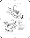
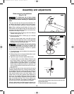
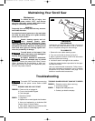
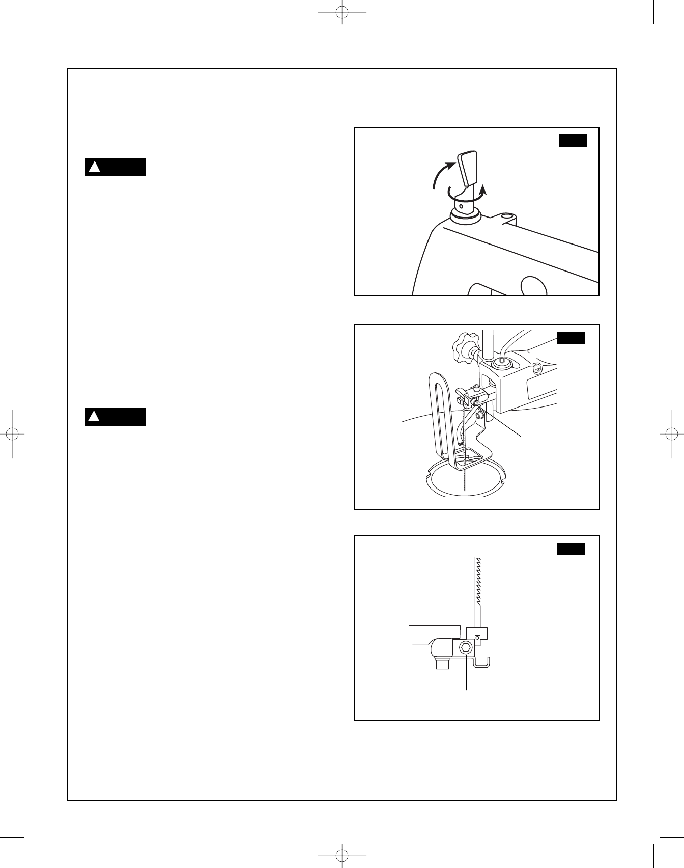
Blade removal and installation
(Fig. 13–15)
To reduce the risk of injury always
turn saw OFF and disconnect the plug
from the outlet before removing or replacing the
b
lade.
This saw uses both pin-end and plain-end blades. Pin-
end blades are thicker for stability and for faster assem-
bly. They provide faster cutting on a variety of materials.
Note: When installing pin-end blades, the slot on the
blade holder must be slightly wider than the thickness of
the blade. After the blade is installed, the blade tension
mechanism will keep it in place.
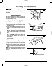
1. Release blade tension by lifting up the Quick Release
Tension Lever
(1) (Fig. 13).
2. Remove the table insert. Carefully pry up on the table
insert and remove.
3. Loosen the upper blade holder screw
(2) and lower
blade holder screw (3). Push down on the upper blade
holder to remove the blade from the holder. Remove
the blade from the lower blade holder.
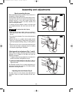
Install the blade with the teeth pointing
downward. If the blade is installed with
the teeth pointing upward, the workpiece will tend to pull
up from the table and will lead to vibration or possible
loss of control of the workpiece.
4. To install the blade, hook the blade in the recess of the
lower blade holder.
5. While pushing down on the upper blade holder, insert
-
the blade into the slot of the holder.
6. Tighten the upper and lower blade holder screws.
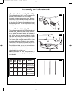
7. To tension blade, move Quick Release Tension Lever
(1) to “down” position. As the lever is lowered, tension
will be applied to the blade. Make sure the blade is
properly located in the blade holders. Turn the blade
tension knob an additional one full turn clockwise. This
amount of blade pressure should do well for most cut-
ting operations.
ATTENTION: Moving the lever downward should require
moderate, steady pressure only. If heavy pressure is need-
ed, the blade is too tight. Loosen tension by rotating the
Quick Release Tension Lever counterclockwise 1-2 turns,
then reset the tension lever to the “down” position. If the
tension lever is in the “down” position and the blade is too
loose, you can increase tension by leaving the tension
lever “down” and rotating it clockwise just until you feel the
slack in the blade removed. Then turn the tension lever
ONE full turn clockwise. This amount of blade pressure
should do well for most cutting operations and blades.
When the blade tension has been properly adjusted, you
should be able to lift up the Quick Release Tension Lever,
remove and install the blade, lower the lever and return the
original blade tension.
8. Snap the table insert back into place.
13.
Assembly and adjustments
FIG. 13
FIG. 14
1
2
3
FIG. 15
WARNING
!
CAUTION
!
SM 2610957121 05-08 6/5/08 7:35 AM Page 13