


-20-
For Machines Mfg. Since 8/09
Model SB1017
OPERATION
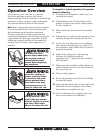
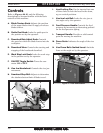
Controls
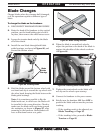
Refer to Figures 20–21 and the following
descriptions to become familiar with the basic
controls of this machine.
A.
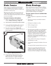
Blade Tension Knob: Adjusts the position
of the upper blade wheel to apply or release
blade tension.
B.
Guide Post Knob: Locks the guide post in
the position set by the operator.
C.
Downfeed Rate Adjust Knob: Controls
the speed at which the blade lowers into the
workpiece.
D.
Downfeed Valve: Controls the starting and
stopping of the headstock downfeed.
E.
Work Stop Lock Knob: Locks the work stop
in the position set by the operator.
F.
ON/OFF Toggle Switch: Turns the saw
motor ON or OFF.
G. V
ise Jaw Handwheel: Controls the vise jaw
movement.
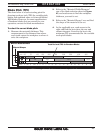
H. D
ownfeed Stop Bolt: Adjusts to determine
the absolute bottom limit of blade travel.
I. He
ad Locking Pin: Can be inserted into one
of three holes to lock the head in the down,
up, or vertical positions.
J. V
ise Jaw Lock Bolt: Locks the vise jaw at
the angle set by the operator.
K. F
eed Pressure Handle: Controls the feed
pressure by increasing or decreasing preload
on the feed pressure spring.
L. Transport Handle: Provides a solid control
point for moving the machine.
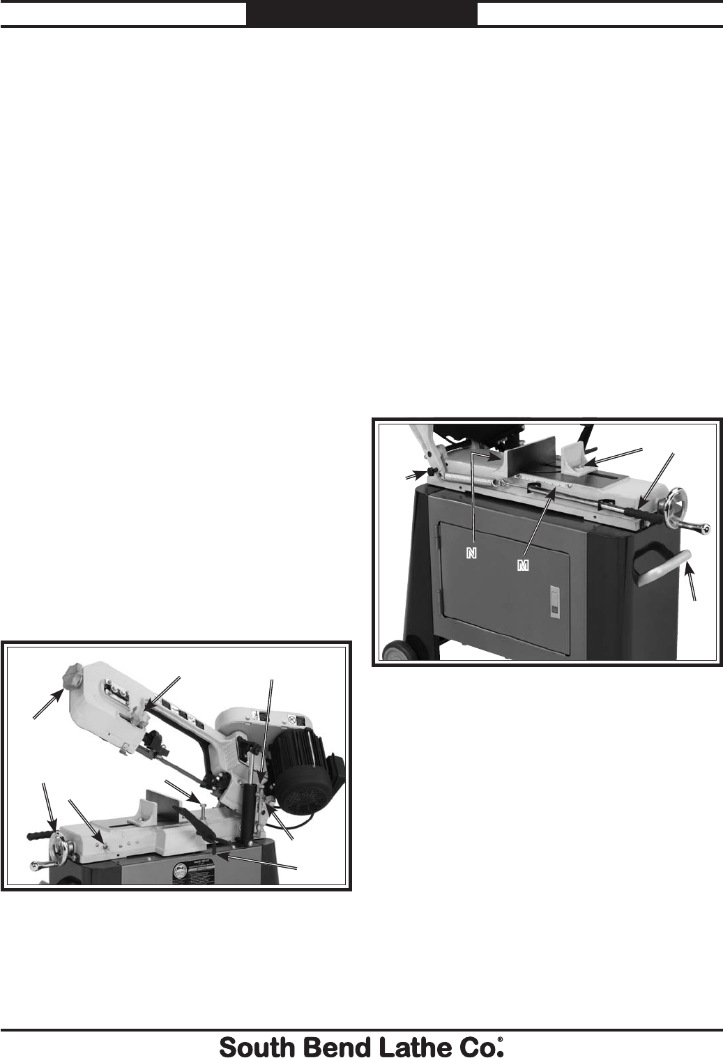
M.
Fence Scale: Indicates the angle of the vise
fence.
N. Vi
se Fence Bolts (behind fence): Lock the
fence at the angle set by the operator.
A
H
G
F
B
C
D
E
Figure 20. Front Identification.
Figure 21. Rear Identification.
I
J
L
K
N
M