


For Machines Mfg. Since 8/09 SB1024/SB1025/SB1026
-35-
OPERATION
Note: Generally, the goal in the next steps is to
get the difference of the indicator readings
between the end of the parallel bar down to
0.0005". However, the acceptable variance
will depend on the requirements for your
operation.
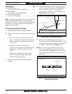
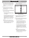
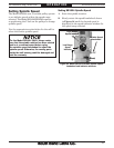
6. Rotate the spindle by hand so that the
indicator point rests on one end of the
parallel block, as illustrated in Figure 27,
then zero the dial.
7. Rotate the spindle so that the indicator point
rests in the same manner on other end of the
block, then read the dial.
— If the indicator dial still reads zero or is
within the acceptable variance, continue
on with Step 8.
— If the indicator dial has moved from zero
beyond the acceptable variance, you will
need to compensate for that amount by
rotating the head left or right. Repeat
Steps 5–6 until you are satisfied with the
spindle axis alignment along the table
X-axis.
Note: Keep one of the rotation lock bolts
just snug so that the head does not move
loosely while you adjust it small amounts.
Remember to tighten the rotation lock
bolts after adjusting the head.
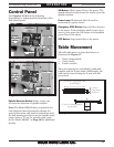
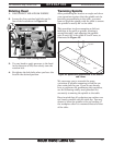
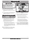
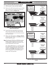
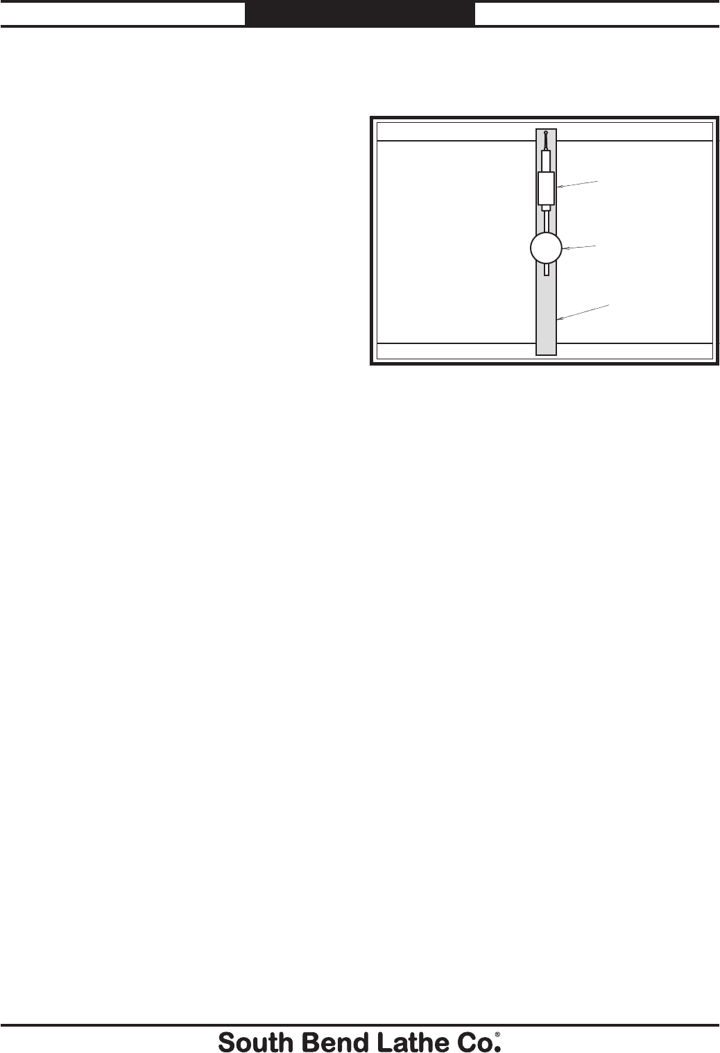
Figure 28. Parallel block positioned for the Y-axis
measurement (top view).
Parallel Block
Indicator
Spindle
Table (Top View)
8. Place the parallel block directly under the
spindle and across the width of the table, as
illustrated in Figure 28.
9. Rotate the spindle so that the indicator point
rests on the parallel bar, as illustrated in
Figure 28, then zero the dial.
10. Rotate the spindle so that the indicator point
rests on the other end of the bar in the same
manner, then read the dial.
— If the indicator dial still reads zero or
is within the acceptable variance, the
spindle is precisely perpendicular to the
table in both the X- and Y-axes and the
tramming procedure is complete.
— If the indicator dial has moved from zero
beyond the acceptable variance, you will
need to compensate for that amount by
tilting the head forward or back. Repeat
Steps 9–10 until you are satisfied with
the spindle axis alignment along the table
Y-axis.
Note: Keep one of the tilt lock bolts just
snug so that the head does not move
loosely while you adjust it small amounts.
Remember to tighten the tilt lock bolts
after adjusting the head.