-42-
For Machines Mfg. Since 8/09
SB1024/SB1025/SB1026
OPERATION
Setting SB1025/SB1026 Spindle Speed
1. DISCONNECT MILL FROM POWER!
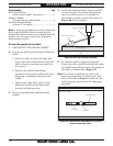
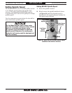
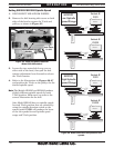
2. Remove the belt housing side covers on both
sides of the head to expose the V-belt and
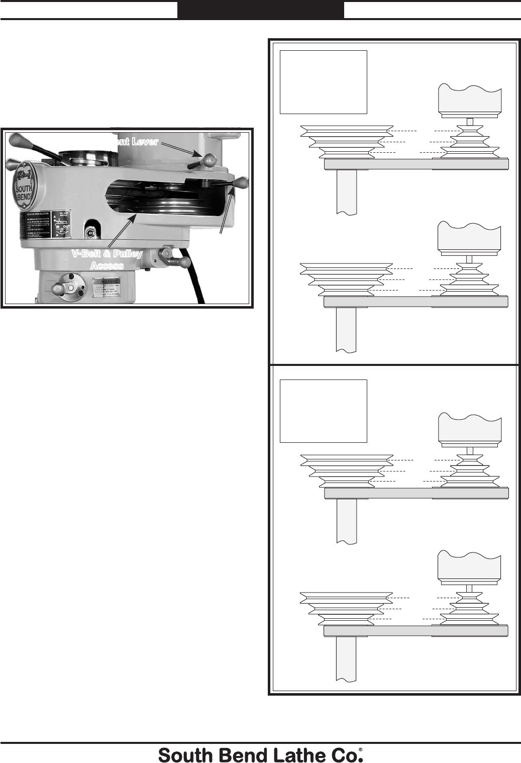
pulleys, as shown in Figure 35.
3. Loosen the two motor lock levers, one on
either side of the head, then pull the belt
tension adjustment lever forward to release
the V-belt tension.
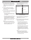
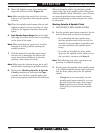
4. Refer to the illustrations in Figures 36–37
and position the V-belt on the pulleys for the
desired spindle speed.
Note: The Models SB1025 and SB1026 produce
slightly different spindle speeds for each
V-belt position. Make sure you refer to the
correct illustration for the mill.
Also, Model SB1025 has two spindle speeds
for each V-belt position that are selected by
using the spindle direction switch on the
control panel. F1/R1 will produce the lower
of the two speeds for each spindle speed
range and V-belt position.
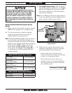
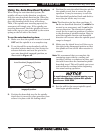
Figure 36. Model SB1025 V-belt positions and
speeds.
Motor
Spindle
Spindle
Motor
Switch @
F1/R1
SB1025
Low Spindle
Speed Range
Switch @
F2/R2
Motor
Spindle
Spindle
Motor
Switch @
F1/R1
Switch @
F2/R2
80
140
220
325
650
160
280
440
710
1170
1860
2800
1420
2340
3720
5600
SB1025
High Spindle
Speed Range
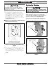
Figure 35. V-belt and pulleys exposed
(Model SB1026 shown).
Adjustment Lever
Lock Lever
(1 of 2)
V-Belt & Pulley
Access


