


For Machines Mfg. Since 8/09 SB1024/SB1025/SB1026
-55-
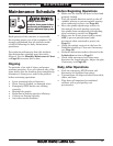
MAINTENANCE
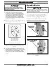
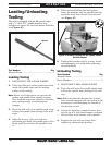
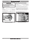
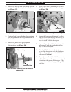
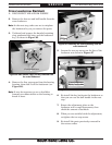
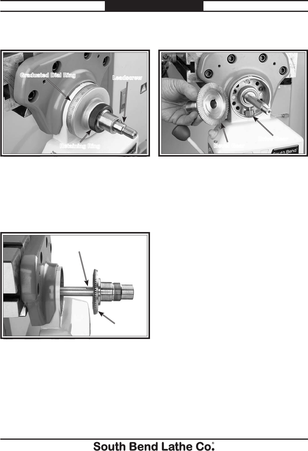
2. Remove the hex nut and ball handle from the
power unit end of the longitudinal leadscrew
(see Figure 57).
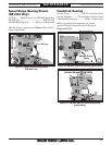
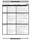
3. Unthread and remove the knurled retaining
ring and graduated dial ring from the end of
the leadscrew.
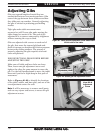
4. Remove the brass bevel gear from the
leadscrew, then remove the leadscrew
alignment key (see Figure 58).
Figure 57. Power feed ball handle removed.
Graduated Dial Ring
Retaining Ring
Leadscrew
Figure 58. Power feed brass gear and leadscrew
alignment key.
Alignment Key
Brass Bevel Gear
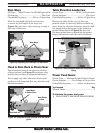
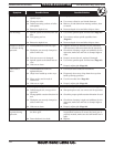
5. Brush a light coat of lubricant on the teeth
of the bevel gear and the smaller drive gear
(see Figure 59).
6. Replace the leadscrew alignment key, then
align the bevel gear keyway and the key as
you slide the gear onto the leadscrew and
mesh its teeth with the drive gear.
7. Replace the graduated dial ring into position
and secure it with the knurled retaining
ring—do not overtighten.
8. Slide the ball handle onto the leadscrew
as you align its keyway with the leadscrew
alignment key, then secure it with the hex
nut removed in Step 2.
9. Manually move the table with the power feed
ball handle to check the gear movement and
to distribute the grease on the gears. If the
movement is not smooth, repeat Steps 2–8
until it is.
Figure 59. Power feed brass gear and drive gear.
Drive Gear
Bevel Gear