


-4-
For Machines Mfg. Since 5/11
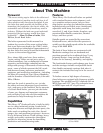
13" Heavy 13
®
Gearhead Lathe
INTRODUCTION
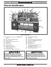
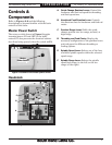
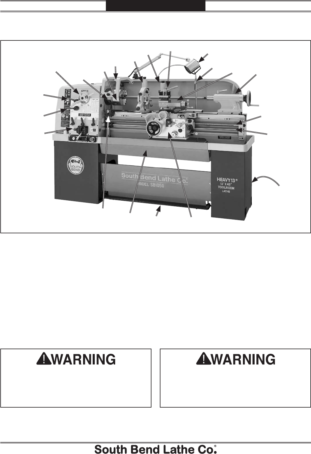
General Identification
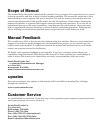
L. Longitudinal Leadscrew
M. Feed Rod
N. Coolant Reservoir & Pump Access
O. Carriage (see Page 6 for details)
P. Safety Foot Brake
Q. Chip Drawer
R. Micrometer Stop
S. Quick-Change Gearbox Controls
(see Page 5 for details)
T. Headstock Feed Direction Lever
U. Gearbox Range Lever
A. Spindle Speed Levers (see Page 50 for
details)
B. D1-5 Camlock MT#5 Spindle
C. 3-Jaw Chuck 8"
D. Chuck Guard w/Safety Switch
E. Steady Rest
F. Follow Rest
G. 4-Way Tool Post
H. Halogen Work Lamp
I. Coolant Nozzle & Valve
J. Compound Rest
K. Tailstock (see Page 7 for details)
Serious personal injury could occur if
you connect the machine to power before
completing the setup process. DO NOT
connect power until instructed to do so later
in this manual.
Untrained users have an increased risk
of seriously injuring themselves with this
machine. Do not operate this machine until
you have understood this entire manual and
received proper training.
Figure 1. Identification.
A
B
C
D
E
F
G
H
I
J
K
L
M
N
O
P
Q
R
S
T
U