


-78-
For Machines Mfg. Since 5/11
13" Heavy 13
®
Gearhead Lathe
SERVICE
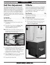
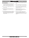
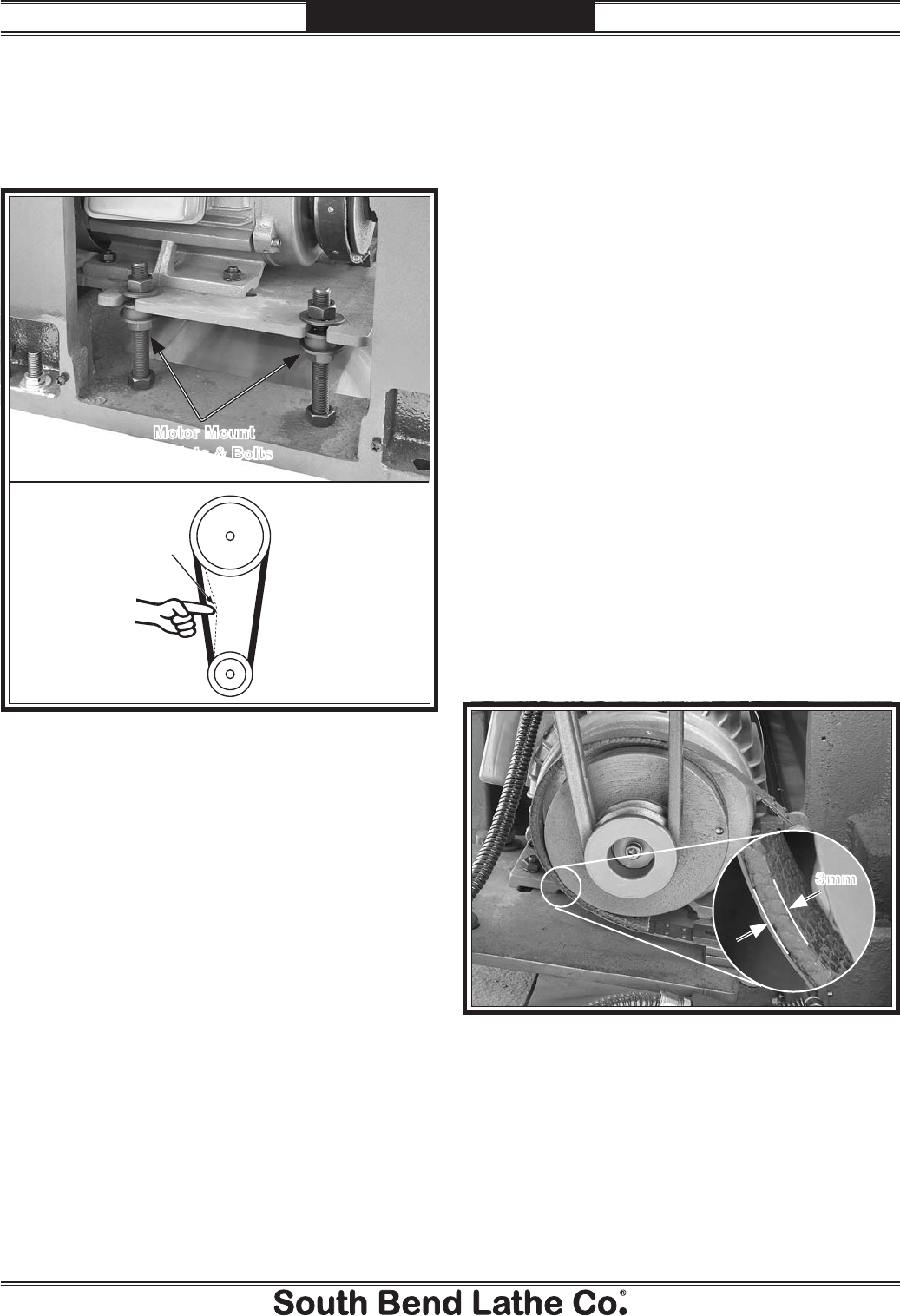
3. Adjust the hex nuts on the motor mount
bolts shown in Figure 123, until there is
approximately
3
⁄4" deflection of the V-belts
when moderate pressure is applied midway
between the pulleys.
4. Firmly tighten the hex nuts to secure the
setting, then re-install the covers.
Pulley
Deflection
Pulley
Motor Mount
Hex Nuts & Bolts
Figure 123. Adjusting V-belt tension.
Brake & Switch
As the brake lining wears, the foot pedal
develops more travel. If the brake band is not
adjusted to compensate for normal wear, the
limit switch will still turn the lathe off, but the
spindle will not stop as quickly. It is especially
important that the brake is kept properly
adjusted so you can quickly stop the spindle in
an emergency.
Tools Needed: Qty
Phillips Screwdriver #2 ........................................1
Hex Wrench 6mm .................................................1
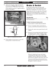
To adjust the brake and brake switch:
1. DISCONNECT LATHE FROM POWER!
2. Put on a respirator and eye protection to
protect yourself from hazardous brake dust.
3. Remove the motor access panel from the left
cabinet.
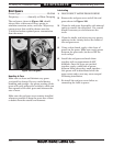
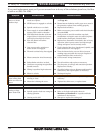
4. Measure the remaining brake band lining at
the thinnest point, which is usually at the
8 o'clock position, as shown in Figure 124.
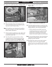
When the brake band is new, the lining
is approximately 6mm thick. If the lining
thickness wears to 3mm or less, the brake
band must be replaced. Otherwise, the rivets
that secure the lining to the band will soon
grind into the brake hub. If the hub becomes
damaged, it must be replaced.
Figure 124. Minimum brake belt thickness.
3mm