


-54-
For Machines Mfg. Since 5/11
13" Heavy 13
®
Gearhead Lathe
OPERATION
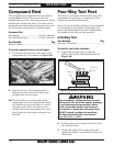
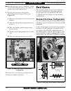
Note: In the next step, use the chuck key to rock
the spindle back and forth to help mesh the
gears as you make adjustments.
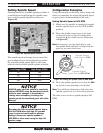
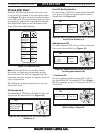
4. Position the controls as directed by
the configuration string as follows (see
Figure 72):
L Move the feed range lever to the low (Low)
position.
C Point the left quick-change gearbox lever
to the C.
S Move the middle quick-change gearbox
lever to the S.
8 Position the bottom gearbox lever in the 8
slot.
W Point the right gearbox lever to the W.
The lathe is now set up for a power feed rate of
0.18mm per spindle revolution.
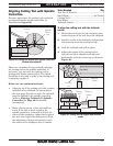
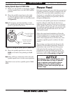
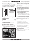
The end gears can be setup for the standard or
alternate configuration, depending upon the
type of operation to be performed. The lathe
is shipped with the end gears in the standard
configuration.
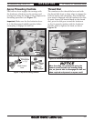
Standard End Gear Configuration
Use the standard end gear configuration for inch
threading, metric threading, and all general feed
operations.
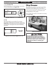
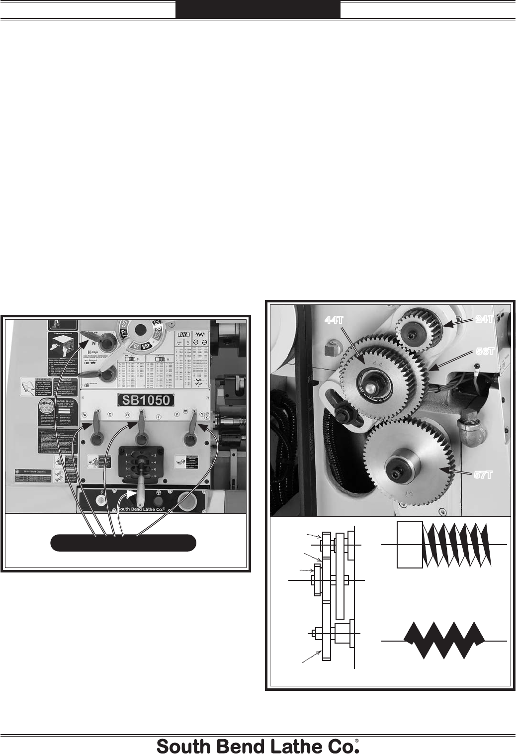
In this configuration, the end gears are installed
as follows: the 24T end gear is installed in the
top position, the 44T/56T transposing gears in
the middle position, and the 57T end gear in the
bottom position, as shown in Figure 73. In this
configuration the 56T and 57T gears are meshed.
End Gears
24T
44T
56T
57T
Figure 73. End gears in the standard configuration.
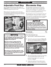
57T
56T
24T
Inch and Metric Pitch
Threading
Inch and Metric Feeding
44T
Figure 72. Power feed controls positioned for
0.18 mm/rev.
.18 LCS8W .007