


6 7
SAVE THESE INSTRUCTIONS FOR FUTURE USE
F
D
C
B
B
H
E
H
A
J
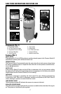
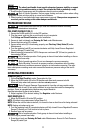
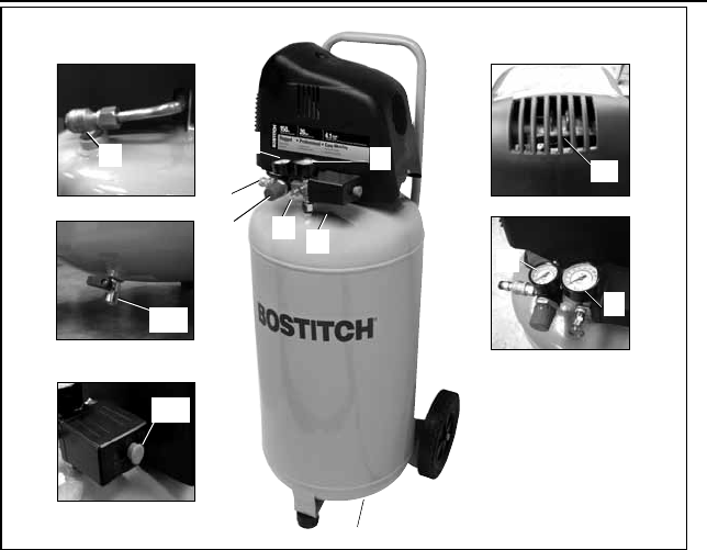
Components (Fig. 1)
A. On(I)/Off(O)Switch F. CheckValve
B. Air Tank Pressure Gauge G. Safety Valve
C. Regulated Pressure Gauge H. Air Tank Drain Valve
D. Pressure Regulator I. Pressure Switch
E. QuickConnect J. Muffler/IntakeFilter
Features (FIG. 1)
ON/OFF SWITCH
Placethisswitch(A)intheON(I)positiontoprovideautomaticpowertothePressureSwitch(I)
and OFF(O) to remove power at the end of each use.
PRESSURE SWITCH
The Pressure Switch (I) automatically starts the motor when the air tank pressure drops below
the factory set cut-in pressure. It stops the motor when the air tank pressure reaches the fac-
tory set cut-out pressure.
SAFETY VALVE
If the Pressure Switch (I) does not shut off the air compressor at its cut-out pressure setting,
the safety valve (G) will protect against high pressure by popping out at its factory set pressure
(slightly higher than the Pressure Switch (I) cut-out setting).
CHECK VALVE
When the air compressor is operating, the check valve (F) is open, allowing compressed air
to enter the air tank. When the air compressor reaches cut-out pressure, the Check Valve (F)
closes, allowing air pressure to remain inside the air tank.
TANK PRESSURE GAUGE
The tank pressure gauge (B) indicates the reserve air pressure in the tank.
REGULATED PRESSURE GAUGE
The outlet pressure gauge (C) indicates the air pressure available at the outlet side of the regula-
tor. This pressure is controlled by the regulator.
G
I
C