


TD-8817 ADSL2+ Ethernet/USB Modem Router User Guide
6
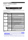
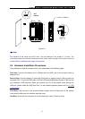
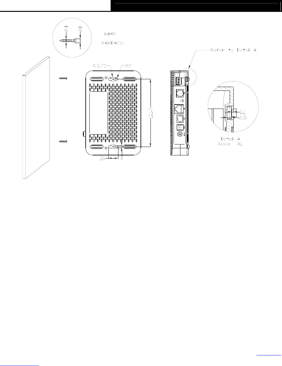
Figure 2-3
Note:
The diameter of the screw, 4mm<D<7.5mm, and the distance of two screws is 111.5mm. The
screw that project from the wall need around 4mm based, and the length of the screw need to be
at least 20mm to withstand the weight of the product.
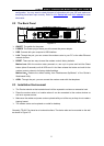
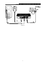
2.4 Hardware Installation Procedures
The procedure to install the modem router can be described in the following steps:
First Step: Connect the Modem port of Splitter with the ADSL port of the modem router by
telephone line.
Second Step: Connect category 5 cable with RJ45 jacks to modem router’s LAN port and your
computer’s NIC. Or connect USB cable to ADSL2+ Ethernet/USB Modem Router’s USB port and
your computer’s USB interface.
(When you connect your PC to the modem router through the
USB port, please install the USB driver first. For the detailed operation please refer to 3.2 USB
Configuration.)
Third Step: Plug one end of the provided Power Adapter into the Power jack on the modem
router and the other end to a standard electrical outlet.
Last Step: Check the line connection to see if everything is ready. Power up finally.