


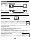
Non-Vehicular or Vehicular Applications
Non-vehicular applications include stationary configurations as well as vehicular configurations that are not integrated into a vehicle’s
electrical system. In a parallel connection, your Inverter/Charger’s Nominal DC Input Voltage must match the voltage of your battery or
batteries. Your 48V DC Inverter/Charger requires 48V DC from your battery system.
In a series connection, your Inverter/Charger’s Nominal DC Input Voltage must match the number of batteries multiplied by their voltage.
Your 48V DC Inverter/Charger requires either four 12V batteries connected in series (48 = 4 × 12) or eight 6V batteries
connected in series (48 = 8 × 6).
In vehicular applications, your Inverter/Charger’s Nominal DC Input Voltage must match the voltage of your battery or batteries—
48 Volts. Although it is possible to connect your Inverter/Charger to the main battery within your vehicle’s electrical system, in the normal
vehicular context, the Inverter/Charger is connected to one or more dedicated auxiliary (house) batteries which are isolated from the drive
system to prevent possible draining of the main battery.
Contact Tripp Lite technical support for assistance with additional parallel, series or series/parallel connections.
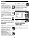
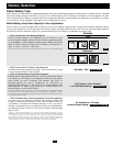
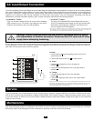
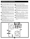
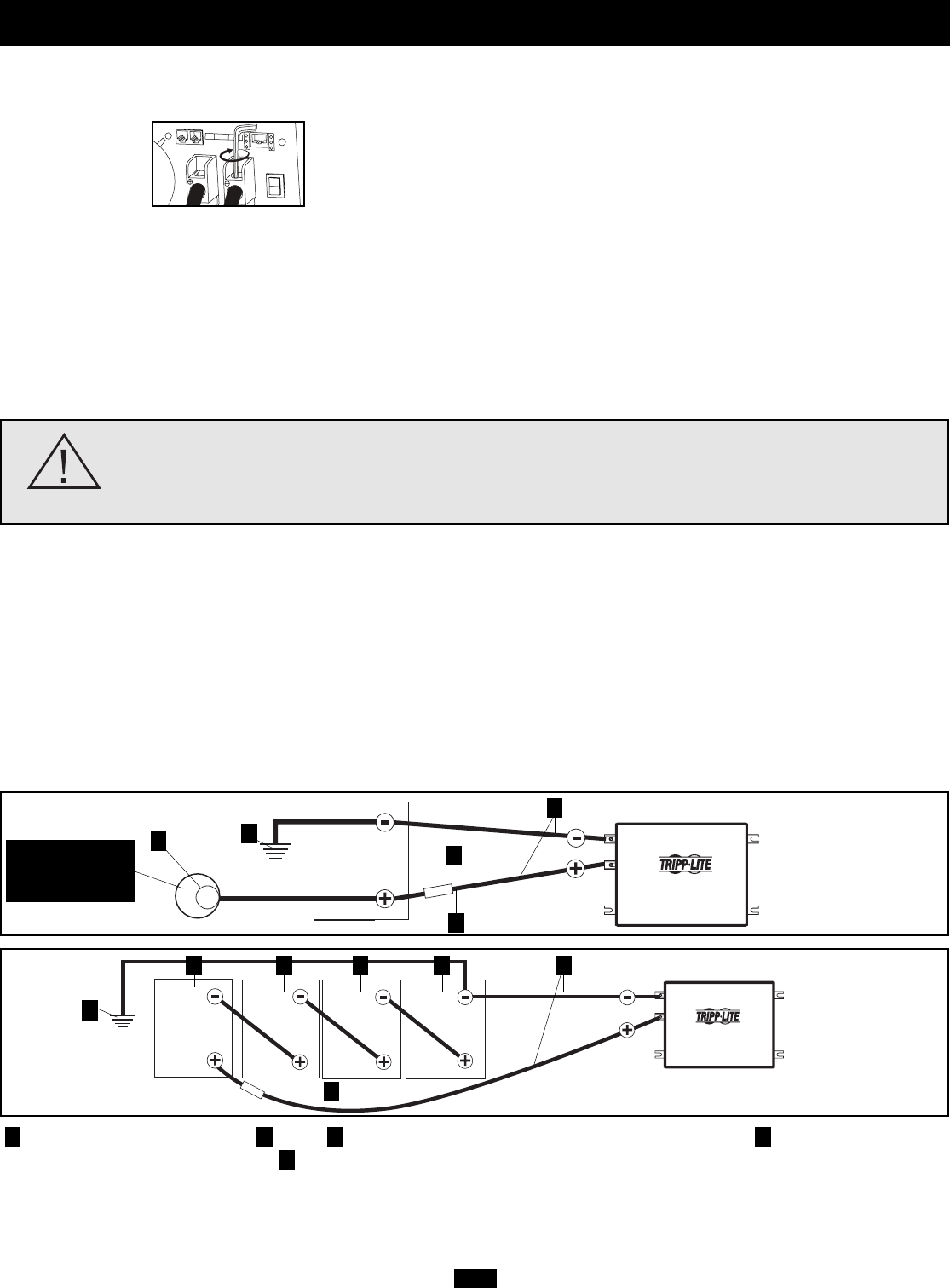
Earth or Vehicle/Boat Battery Ground Battery UL-Listed Fuse & Fuse Block (mounted within 45 cm of the battery) Large Diameter
Cabling, Maximum 00 Gauge to Fit Terminals Alternator (for vehicle or boat connection only)
5
4321
48 Volts Inverter/Charger
48 Volts
Single Battery Connection
4
1
2
3
48 Volt Inverter/Charger
12 Volts
12 Volts 12 Volts 12 Volts
Multiple Battery Connection (Series)
1
2 2 2 2 4
3
Battery Connection
5
Optional connection
for Vehicular
applications only.
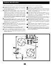
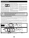
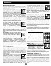
• Connect DC Wiring: Though your
Inverter/Charger is a
high-efficiency
converter of
electricity, its rated
output capacity is
limited by the length
and gauge of the
cabling running from the battery to the unit.
Use the shortest length and largest diameter
cabling (maximum 00 gauge) to fit your
Inverter/Charger’s DC Input terminals.
Shorter and heavier gauge cabling reduces
DC voltage drop and allows for maximum
transfer of current. Your Inverter/Charger is
capable of delivering peak wattage at up to
200% of its rated continuous wattage output
for brief periods of time. Heavier gauge
cabling should be used when continuously
operating heavy draw equipment under these
conditions. Tighten your Inverter/Charger
and battery terminals to approximately 3.5
Newton-meters of torque to create an
efficient connection and to prevent
excessive heating at this connection.
Insufficient tightening of the terminals could
void your warranty. See Specifications
page for Minimum Recommended Cable
Sizing Chart.
• Connect Ground: Using an 8 AWG wire
or larger directly connect the Main Ground
Lug to the vehicle’s chassis or earth ground.
See the Feature Identification section to locate
the Main Ground Lug on your specific
Inverter/Charger model. All installations
must comply with national and local codes
and ordinances.
• Connect Fuse: Tripp Lite recommends
that you connect all of your Inverter/Charger’s
positive DC Terminals directly to a fuse(s)
and fuse block(s) within 45 cm of the
battery. The fuse’s rating must equal or
exceed the Minimum DC Fuse Rating listed
in your Inverter/Charger’s specifications.
See Specifications for fuse and fuse block
recommendations. See diagrams below for
proper fuse placement.
Connect your Inverter/Charger to your batteries using the following procedures:
WARNING! • Failure to properly ground your Inverter/Charger to a vehicle’s chassis or earth
ground may result in a lethal electrical shock hazard.
• Never attempt to operate your Inverter/Charger by connecting it directly to output from an
alternator rather than a battery or battery bank.
• Observe proper polarity with all DC connections.
DC Connectors
8