


6
FinishControl 5000
AUS
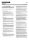
10 BREAKS IN WORK
1. Switch device o with main switch on the basic unit.
2. Insert spray gun into gun mounting on the device.
In using quick-drying or two-component coating
materials, do not fail to rinse unit through with
a suitable cleaning agent during the processing
period.
Important: The application life of the material can
change as a result of heating. Therefore, please
consult the material manufacturer.
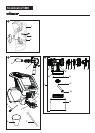
11 TRANSPORTATION
1. Coil power cable around the basic unit.
2. Insert spray gun into gun mounting on the device.
3. Disconnect air hose by pressing the two side clips (Fig. 8).
4. Roll up the air hose and tie up with the xing straps.
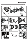
12 TAKING OUT OF OPERATION AND
CLEANING
1. Turn the machine o.
2. Divide the spray gun. Press catch (Fig. 2, A) down slightly.
Twist spray attachment and gun handle towards each
other.
ATTENTION! Electrical contacts in gun
handle. Never hold the gun handle under
water or immerse it into liquids.
Clean the housing only with a moistened
cloth.
3. Unscrew the container.
Empty the remaining coating material into the original
container.
4.
Pre-clean the container and feed tube using a
brush and suitable cleaning agent.
Clean the ventilating bore. (Fig. 9, 2)
5.
Pour solvent or water into the container. Screw the
container back on.
Do not use flammable materials for cleaning
purposes.
6. Connect spray attachment and gun handle. (Fig. 2)
7. Switch device on and ush spray attachment through with
solvent or water.
Repeat the above procedure until the solvent or water
emerging from the nozzle is clear.
8. Turn o the machine and divide the spray gun.
9.
Screw o the container and empty it.
Unscrew feed tube with container seal. (Fig. 11)
10.
Clean feed tube and suction nozzle in spray attachment
with cleaning brush. (Fig. 12)
CAUTION! Never clean seals, diaphragm
and nozzle or air holes of the spray gun
with metal objects.
The ventilation hose and diaphragm are
only solvent-resistant to a limited extent.
Do not immerse in solvent, only wipe.
11.
Remove the adjusting ring (fig. 13,1) carefully from
the union nut (2). Unscrew union nut (2), remove
air cap (3), nozzle (4) and nozzle seal (5).
Thoroughly clean all parts.
Take special care when cleaning the interstices on
the needle (Fig. 14)
12.
Clean the outside of the spray gun and container with a
cloth soaked in solvent or water.
13. Assemble the parts again (see “Assembly”).
12.1 ASSEMBLY
ATTENTION! Follow the steps described
below exactly for assembly. Otherwise
the spray attachment may be damaged.
1. Push nozzle seal onto the needle so that the groove (slot)
points away from the spray attachment. (Fig. 15)
2.
Place nozzle on the needle with recess downwards.
Attention if using WallSpray or StandardSpray:
Position of needle must be congruent with the nozzle
aperture. (Fig. 16)
3. Place air cap on nozzle (pay attention to recesses in the air
cap). (Fig. 17)
4. Screw on union nut. (Fig. 18)
5.
Snap the adjusting ring into the union nut. (Fig. 19)
Make sure that the two recesses on the adjusting ring
are engaged in the air cap clamps and that the lever for
adjusting the spray jet width is located on the pin.
6. Place the container seal from below on the feed tube and
slide it over the collar, while turning the container seal
slightly.
7. Screw the feed tube with the container seal into the body
of the gun.
In order to mount the gun more easily apply
lubricating grease (enclosed) liberally to the O-ring
at the spray attachment and to the O-ring of the
plug connection of the air hose (Fig. 20).
BREAKS IN WORK/ TRANSPORTATION/
TAKING OUT OF OPERATION AND CLEANING