


3
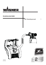
FinishControl 5000
AUS
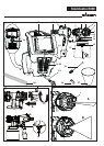
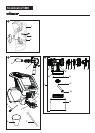
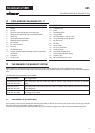
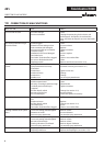
2 EXPLANATORY DIAGRAM FIG. 1
3 THE WAGNER CLICK&PAINT SYSTEM
POS.
DESIGNATION
1 Nozzle
2 Air cap
3 Spray jet width adjusting lever (shaping air)
4 Spray jet level adjusting ring (vertical/horizontal)
5 Union nut
6 Spray attachment complete
7 Material volume regulation
8 Gun handle
9 Air volume control
10 Air hose
11 Click&Paint catch
12
Trigger (actuates turbine starting switch
material is
conveyed)
13 Container
14 Suction tube
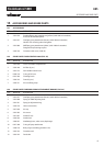
POS.
DESIGNATION
15 Container seal
16 Valve
17 Ventilating hose
18 Carry handle
19 ON/OFF switch (I = ON, 0 = OFF)
20 Gun mounting for park position
21 Air lter cover
22 Air lter
23 Power cable
24 Air hose connection
25 Cleaning brush
26 Fine feed tube lter (red)
Coarse feed tube lter (white)
27 Funnel (3 pcs.)
28 Air hose xing straps (2 pcs.)
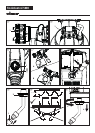
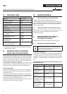
With the Wagner Click&Paint System, the front part of the gun (spray attachment) can be replaced quickly and easily.
This enables a rapid material change without cleaning, and ensures that the right tool is available for every material and applica-
tion.
The following spray attachments are available:
Spray attachment Area of application
StandardSpray (yellow)
Order No. 2321 879
Spray attachment with slit nozzle and 1000 ml stainless steel container. Processes all standard
paints.
FineSpray (brown)
Order No. 2321 877
Spray attachment with round nozzle and 1000 ml stainless steel container. Ideal for low-viscosity
paints and glazes.
WallSpray (white)
Order No. 2321 880
Interior wall paint spray attachment with slit nozzle and 1400 ml plastic container. Designed for
processing acrylic paints.
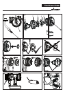
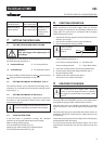
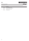
3.1 DISASSEMBLY OF THE SPRAY GUN
For assembly, insert the spray attachment into the gun handle so that the two arrows point at each other. Turn the gun handle
90° in the arrow direction until it audibly engages. (Fig. 2)
To remove the spray attachment, push the catch (Fig. 2, A) beneath the trigger down and turn the spray attachment by 90°.
EXPLANATORY DIAGRAM/ CLICK&PAINT SYSTEM