


25
B_04121
8
1
3
4
7
7
6
5
9
8
10
11
13
12
2
14
OPERATING MANUAL
VERSION 03/2013 ORDER NUMBER DOC 2310799
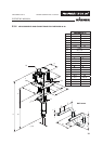
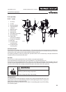
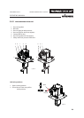
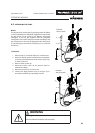
5.4.1 PUMP
5.4 FUNCTION
Fluid section (6)
The uid section has been designed as a piston pump with exchangeable ball valves. The
pump piston runs in two xed packings which are self-adjusting by means of a pressure
spring, thus resulting in a long service life.
Between the air motor and the uid section there is a separating agent cup (4) for holding
the separating agent.
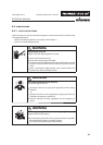
Function principle
The piston pump is driven with compressed air (11). This compressed air moves the air piston up and down in
the air motor (1) and it also moves the associated pump piston up and down in the uid section (6). At the end
of each stroke, the compressed air is redirected by a reversing valve (9).
The working material is sucked up during the upwards stroke and is continuously conveyed towards the
material outlet (5) in both stroke directions.
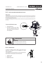
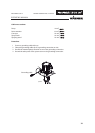
Air motor
The air motor (1) with its pneumatic reverse (9) does not require pneumatic oil.
The compressed air is fed to the motor via an air regulator (11) and the ball valve (12).
The air motor is to be equipped with a safety valve (10) in accordance with Chapter 5.4.3. The safety valve (10)
has been set and sealed at the factory. In case of pressures over and above the permissible operating pressure,
the valve, which is held with a spring, automatically opens and releases the excess pressure.
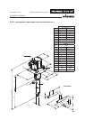
1 Air motor
2 Air inlet
3 Mounting ange
4 Separating uid
container
5 Material outlet
6 Fluid section
7 Material inlet
8 Grounding connection
9 Reversing valve
10 Safety valve
(air motor ventilation)
11 Air pressure regulator
12 Ball valve
13 Air outlet to the
reversing valve
14 Air inlet into the
reversing valve
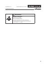
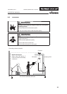
Overpressure!
Risk of injury from bursting components.
Never change the safety valve setting.
WARNING