


INSTALLATION
MAIN PIPING CONNECTIONS
Refer to warnings and cautions on page 2 before
attempting installation. All piping must comply with local codes,
ordinances, and/or national fuel gas codes.
1. Turn off electrical power to the system at the fuse box or
circuit breaker. Also turn off the main gas supply.
2. If replacing an existing valve, disconnect all plumbing and
electrical connections from the old control.
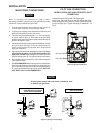
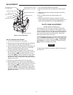
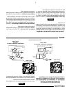
3. This valve may be installed upright, + or – 90˚ from upright,
or vertical (refer to figure 1). The arrows on the valve iden-
tification label and on the bottom plate indicate direction of
gas flow through the valve
4. You should use new pipe that is properly chamfered, reamed,
and free of burrs and chips. If you are using old pipe, be
sure it is clean and free of rust, scale, burrs, chips, and old
pipe joint compound.
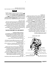
5. Apply pipe joint compound (pipe dope) or teflon tape that is
approved for all gases, only to the male threads of the
pipe joints. DO NOT apply compound or teflon tape to the
first two threads (see fig. 3 for typical piping connections).
6. Do not tighten piping excessively, as this may damage the
valve (50ft lbs max).
7. See SYSTEM WIRING when making electrical connections.
After all gas and electrical connections are completed, turn
gas on and check for gas leaks with leak detection solution
or soap suds. Bubbles forming indicate a leak. SHUT OFF
GAS AND FIX ALL LEAKS IMMEDIATELY.
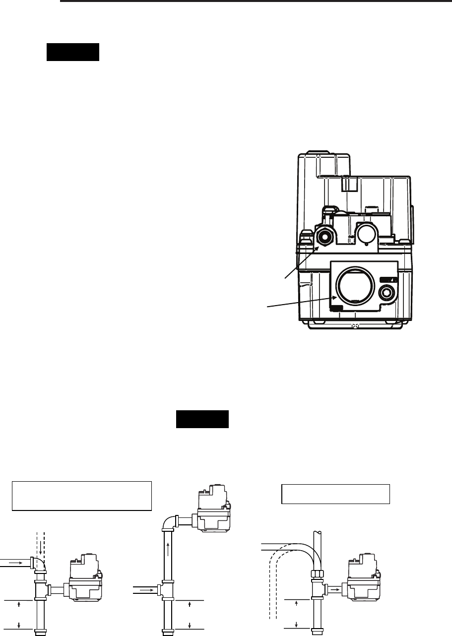
PILOT GAS CONNECTION
MODELS 36H3X AND 36H6X REQUIRE A PILOT
CONNECTION.
Loosen the pilot fitting until it is finger-tight.
Insert clean, deburred tubing all the way through the fitting.
While holding the tubing securely, slowly tighten fitting until
you feel a slight “give”. Tighten the fitting an additional 1 1/2
turns.
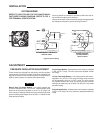
All piping must comply with local codes, ordinances, and/
or national fuel gas codes.
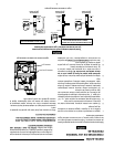
Piped Gas
Supply
Piped Gas
Supply
Tubing Gas
Supply
NOTE: ALWAYS INCLUDE A
DRIP LEG IN PIPING
Figure 2. Typical gas valve piping
NOTE: A MANUAL SHUTOFF VALVE
MUST BE INSTALLED WITHIN
6 FEET OF THE EQUIPMENT
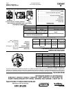
Horizontal
Drop
Gas Valve
3 in.
minimum
Gas Valve
Riser
3 in.
minimum
Drop
Horizontal
Riser
Gas Valve
3 in.
minimum
3
Figure 3. typical gas valve piping
Pilot Gas Outlet
Gas Outlet
Figure 2. gas valve outlet end
Figure 2. gas valve outlet end
NOTE
NOTE