


11
Maintenance
This section provides procedures required to main-
tain the belt/disc sander. The numbers in parenthe-
ses throughout the manual correspond with reference
numbers for parts shown in the exploded views in the
Replacement Parts section.
Lubrication
The bearings used in the sanding machine are
sealed, pre-lubricated bearing. The bearings do not
require periodic lubrication.
Cleaning
Periodically use a vacuum cleaner to remove sanding
debris from the machine. In hard to reach areas,
brush the debris loose while vacuuming.
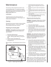
Replacing the Sanding Belt
WARNING: DISCONNECT ELECTRICAL POWER
TO THE MACHINE BEFORE PERFORMING ANY
MAINTENANCE.
1. Disconnect electrical power.
2. Position sanding belt platen (4) in the vertical
position. Remove eight screws (97) and guard
(96).
3. Remove screw (76) and guard (75).
4. Move tensioning lever (50) downward to slacken
sanding belt (79).
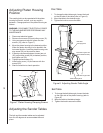
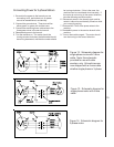
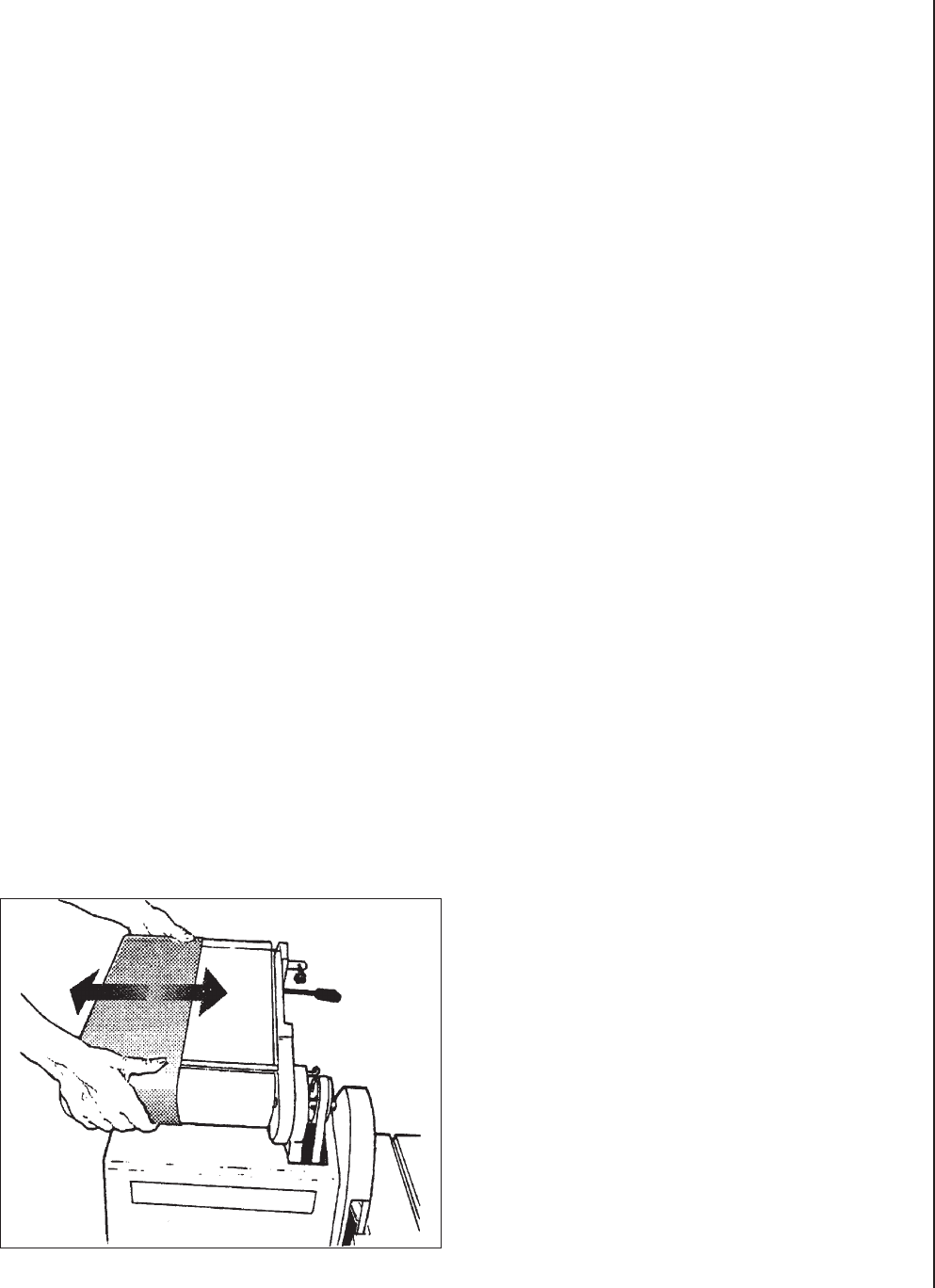
Refer to Figure 9. Slip sanding belt off drums (5) and
(39).
Figure 9. Replacing Sanding Belt
1. Install replacement sanding belt on drums.
Position edges of sanding belt evenly on the
drums.
2. Lift tensioning lever to tighten sanding belt on
drums.
3. Install guard (75) and secure with screw (76).
4. Install guard (96) and secure with eight screws
(97).
5. Connect electrical power and operate machine to
check operation.
6. If belt does not track properly, adjust tracking
(refer to Adjusting Belt Tracking).
Replacing the Sanding Disc
WARNING: DISCONNECT ELECTRICAL POWER
TO THE MACHINE BEFORE PERFORMING ANY
MAINTENANCE.
1. Disconnect electrical power.
2. Loosen screw (65). Remove disc table (60).
3. Remove four screws (56) and plate (55) from
disc shroud (53).
4. Insert a long T-handle Allen wrench through the
side opening in shroud (53) and into set screw
(57). Loosen disc set screw (57) and remove
disc (58).
WARNING: USE CARE WHEN USING KNIFE TO
SEPARATE SANDING DISC (59) FROM DISC (58).
INJURY FROM THE KNIFE MAY OCCUR IF THE
KNIFE SLIP OR IF SANDING DISC SHOULD
SUDDENLY COME FREE.
5. Using a knife, slowly work the tip of the knife
blade under sanding disc (59). Slowly work the
tip around the circumference of disc (58).
Continue to work around the circumference until
sanding disc can be separated by hand from
disc (58).
6. Remove paper backing from replacement sand-
ing disc (59). Place sanding disc (59) on disc
(58). Make sure the sanding disc is place evenly
at the outside diameter of disc (58).
7. Press on the sanding disc to remove any en-
trapped air and to make sure the sanding disc is
adhering to disc (58).
8. Install disc (58) onto shaft (16). Position the disc
on the shaft to provide clearance between plate
(55) and sanding disc. Tighten set screw (57).
NOTE: There is a close fit between the edge of disc
(58) and disc shroud. To ease installation and posi-
tioning of the disc, use an L-shaped tool (such as an
Allen wrench) under outer edge of the disc to support
and position the disc while tightening set screw.