


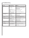

12
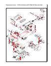
9. Install plate (55) and secure with four screws
(56). Check for clearance between plate (55)
and the sanding disc.
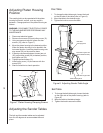
10. Install table (60) onto rod (74). Position table so
it is level and tighten screw (65) against rod (74).
11. Connect electrical power and operate machine to
check operation.
Replacing the V-Belts
WARNING: DISCONNECT ELECTRICAL POWER
TO THE MACHINE BEFORE PERFORMING ANY
MAINTENANCE.
1. Disconnect electrical power.
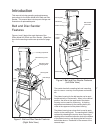
2. Remove sanding belt table.
3. Remove sanding disc table.
4. Remove sanding disc and shroud.
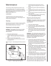
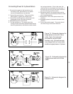
5. Remove pulley cover. Loosen set screw in pulley.
6. With second person holding belt housing,
alternately loosen and remove two screws.
7. Remove V-belt from pulley (11). Remove pulley
from shaft while separating assembled belt
housing from the machine base.
8. Remove key from sanding belt drum shaft.
9. Loosen set screw in pulley (20).
10. Remove pulley. While removing pulley, slip V-
belts from pulley.
11. Remove four screws from base. With assistance
of the second person, lift base from stand.
NOTE: Place base on bench. As an alternative, the
stand may be used to support the base while remov-
ing drive motor screws.
12. Place base on bench with underside of the base
facing up.
13. Remove two hex head screws, two nuts, and two
washers from the motor base on the shaft side of
motor.
14. Loosen (but do not remove) two hex bolts, two
nuts, and two washers on the side of motor base
opposite the motor shaft.
15. Tip motor enough to provide clearance between
end of shaft and wall of base. Remove motor
drive belt.
16. With base still on the bench, slip V-belt (15) over
end of idler shaft.
NOTE: Install V-belt for sanding belt first, followed by
the motor V-belt.
17. Install replacement V-belt over end of motor shaft.
18. Install two hex bolts, two nuts, and two washers in
the motor base on the shaft side of motor.
Tighten all four hex nuts and hex head screws.
19. Install key in idler shaft with keyway facing up.
Install pulley (20) on idler shaft.
20. Install motor V-belt (18) in outermost groove of
pulley (20) and on pulley (18) on motor shaft.
21. Position motor belt (18) on idler shaft so it is
parallel with the inner wall of the base. Tighten
set screw in pulley (20).
22. Place assembled base on stand. Secure with
four screws, washers, nuts.
NOTE: Because of the weight of the belt housing, a
second person should hold the belt housing in
position while installing pulley (10).
23. Hold belt housing in position in bracket (3). Start
two screws (13) in threaded holes in platen.
Install key (8) in shaft.
NOTE: Because of the length of screws (13), the
screws will have to be installed alternately. As the
screws are installed, there will be enough clearance
to slide the belt drum drive pulley a little at a time onto
shaft (8).
24. Alternately install two screws (13). As the screws
are tightened, slide pulley (10) onto the idler shaft
as allowed by the protrusion of screw heads.
Make sure V-belt remains on pulleys (11 and 20).
25. When screws (13) are fully installed, align pulley
(20) with pulley (11). Tighten set screw (10).
26. Install shroud (53) on base and secure with four
screws and washers.
27. Install pulley cover (12) and secure with two
screws.
28. Install disc (58) onto shaft (16) and over key.
Position the disc on the shaft to provide clear-
ance between plate (55) and the sanding disc.
Using long T-handle Allen wrench, tighten set
screw (57).
NOTE: There is a close fit between the edge of disc
(58) and the disc shroud. To ease installation and
positioning of the disc, use an L-shaped tool (such as
an Allen wrench) under the outer edge of the disc to
support and position the disc while tightening the set
screw.
29. Install plate (55) and secure with four screws
(56). Check for clearance between plate (55)
and the sanding disc.
30. Install table (60) onto rod (74). Position table so
it is level and tighten screw (65) against rod (74).
31. Install assembled table (88).
32. Connect electrical power and operate machine to
check operation.