


8
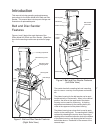
The disc sander consists of an aluminum disc onto
which is installed an adhesive-backed sanding and
other abrasive discs. The disc is contained within a
ducted shroud.
The sanding disc can be replaced by removing the
table and a cover over the lower portion of the disc.
If desired, the aluminum disc can be removed from
its drive shaft to ease replacement of the sanding
disc.
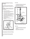
The drive motor for the belt and disc sander is
attached to the underside of the machine base. An
ON/OFF switch is mounted on the machine base on
the side opposite the disc sander. Electrical wiring
for the motor enters the machine base below the ON/
OFF switch and is routed to the switch and motor
inside the machine base.
The belt and disc sander is driven by V-belts con-
nected to the drive motor. A pulley on the motor shaft
drives a V-belt that drives a dual-groove pulley on an
idler shaft. A second V-belt is installed in the second
groove of the dual-groove pulley and connects to a
pulley on belt sander drive shaft.
The aluminum sanding disc is driven off the end of
the idler shaft. A shaft connected to the second V-
belt pulley drives the belt sander drive drum.
The belt and disc sander is mounted on a stand that
can be secured to the floor to stabilize the machine.
The stand has a door for access to the fasteners for
the machine base.
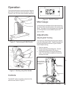
Installation and Setup
Mounting
It is recommended that the belt and disc sander be
secured to the floor for safe operation. The machine
stand has mounting holes in a flange on the inside of
stand enclosure. The stand can be secured to the
floor using these mounting holes.
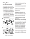
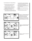
Electrical Connection
Refer to the Wiring Data section for wiring informa-
tion. Electrical power should be connected by a
qualified electrician. Observe local electrical codes
when connecting and grounding the machine.