


10
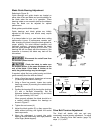
Blade Selection
The cut-off saw is delivered with a saw blade
that is adequate for a variety of cut-off jobs on a
variety of common materials. A 10-tooth,
general-purpose blade is provided as standard
equipment with the machine.
An optional 8-tooth blade and an optional
14-tooth blade are available from Wilton. (Refer
to the Parts section for saw blade part numbers.)
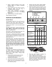
Refer to Figure 5 for the speeds recommended
for various materials. These speeds, while
appropriate for many common shop cutting
needs, do not encompass the wide variety of
special blade configurations (tooth pitch and set)
and special alloys for cutting unusual or exotic
materials.
A coarse blade could be used for a solid steel
bar, but a finer tooth blade would be used on a
thin-wall steel tube. In general, the blade choice
is determined by the thickness of the material;
the thinner the materials; the finer the tooth
pitch.
A minimum of three teeth should be on the
workpiece at all times for proper cutting. The
blade and workpiece can be damaged if the
teeth are so far apart that they straddle the
workpiece.
For very high production on cutting of special
materials, or to cut hard-to-cut materials such as
stainless steel, tool steel, or titanium, you can
ask your industrial distributor for more specific
blade recommendations. The supplier that
provides the workpiece material should be able
to provide you with very specific instructions
regarding the best blade (and coolant or cutting
fluid, if needed) for the material or shape
supplied.
Blade Break-in Procedures
New blades are very sharp and, therefore, have
a tooth geometry that is easily damaged if a
careful break-in procedure is not followed.
Consult the blade manufacturer’s literature for
break-in of specific blades on specific materials.
However, the following procedure will be
adequate for break-in of Wilton-supplied blades
on lower alloy ferrous materials.
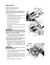
1. Clamp a section of round stock in the vise.
The stock should be 2 inches or larger in
diameter.
2. Operate the saw at low speed. Start the cut
with a very light feed rate.
3. When the saw has completed 1/3 of the cut,
increase the feed rate slightly and allow the
saw to complete the cut.
4. Keep the hydraulic cylinder needle valve in
the same position and begin a second cut
on the same or similar workpiece.
5. When the blade has completed about 1/3 of
the cut, increase the feed rate.
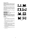
Watch the chip formation until cutting is at its
most efficient rate and allow the saw to
complete the cut (refer to Evaluating Blade
Efficiency on page 10). The blade is now
considered ready for use.
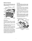
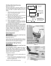
Operations
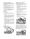
Hydraulic Feed Control
The weight of the saw head provides the force
needed to cut through the workpiece. The cut-off
saw has a hydraulic cylinder that controls the
feed rate of the saw.
The hydraulic feed control circuit consists of a
single acting hydraulic cylinder (Figure 7) and a
feed rate control (Figure 5). The feed control
cylinder resists motion in the downward direction
to control the feed rate. The control cylinder
offers no resistance when raised upward.
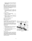
The feed rate control knob (Figure 5) controls
the rate at which the saw head is lowered. The
control knob (needle valve) controls the rate at
which the hydraulic fluid is released from the
hydraulic cylinder. When the needle valve is
closed, the cylinder is locked. With the needle
valve slightly open, the cylinder permits slow, or
light, downward force. Opening the needle valve
further increases the feed rate and applies more
weight to the saw blade and workpiece.
The needle valve is adjusted until the saw is
operating efficiently. The efficiency of operation
is usually evaluated by observing chip formation.
Blade efficiency is further described below.
Figure 7