


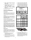

8
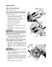
The mechanism also has adjustment screws
that enable the saw blade to “track” evenly on
the blade wheels. The adjustment screws
change the angle of the driven blade wheel shaft
so the wheels are aligned. Tracking adjustments
are generally made after the saw blade is
changed but may be required periodically due to
wear over time.
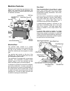
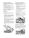
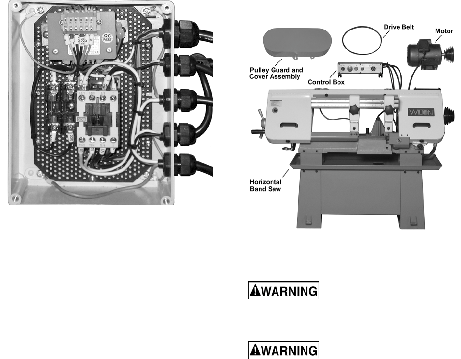
An electrical enclosure is attached to the leg
panel on the right side of the machine. The
enclosure contains the switches and fuses
required for operation and protection of the drive
motor (Figure 3).
Figure 3
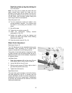
Work Stop
A work stop is provided with the machine to
allow cutting multiple pieces of identical length
(refer to Figure 12). The stop consists of a rod
onto which is installed a stop bracket, a tapered
stop, a clamping knob and a locking handle. The
rod is installed in a bore in the front of the saw
bed. The stop bracket is positioned on the rod
with the tapered stop toward the end of the
workpiece. The bracket is moved in or out on the
rod to establish the length of the workpiece.
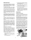
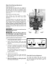
Control Panel
The control panel is mounted on the top of the
saw head. Refer to the Controls and Indicators
section (page 9) for a description of the controls.
Unpacking and Assembly
Machine Setup
The cut-off saw has been pre-adjusted at the
factory and several test pieces have been cut to
verify cutting accuracy.
Remove the saw from the shipping skid; discard
any hold-down devices. Place the saw on the
shop floor; secure the saw to the floor using
mounting anchors secured through four holes in
the machine base. If the saw will be used to cut
long pieces of stock, allow plenty of room for the
length of the stock.
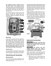
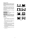
Minimal assembly is required (see to Fig. 4),
consisting of mounting the control box, motor,
pulley guard/cover assembly and motor drive
belt. The mounting hardware is already in place
on the saw head. Loosen or remove the
hardware, placing the components (listed above)
in place and secure. For the drive belt, refer to
the Drive Belt section on page 19.
Figure 4
Electrical Connection
Electrical connection must
be made by a licensed electrician. The wiring
methods and practices must comply with
local electrical codes.
The machine uses high
voltage electrical power that poses a
significant risk of serious injury or death if
proper precautions are not observed
Connect the machine to the electrical power
branch circuit (refer to the Wiring section on
page 31). Observe the following guidelines when
connecting the saw to the power source.
1. Make sure the saw is disconnected from
the electrical power branch circuit (trip the
required circuit breakers or remove the
required fuses).