


Adjustments
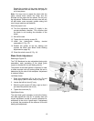
Blade Tracking Adjustment
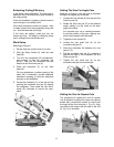
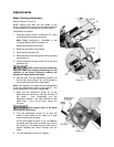
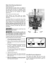
Refer to Figures 13 and 14.
Blade tracking has been set and tested at the
factory. Adjustment is rarely required when the blade
is used properly or if the blade is correctly welded.
If adjustment is needed:
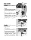
1. Using the blade tension handwheel (D), make
sure the blade is properly tensioned.
Note: Blade tensioning is described in the
Changing Blades section on page 18).
Keep proper tension at all times.
2. Raise the saw head (A) as shown.
3. Open the wheel guards (B).
4. Remove both of the blade-guide bearing bracket
assemblies (C).
5. Loosen three hex locking screws (E) in the head
weldment (G).
While performing the following,
keep the blade from rubbing excessively on the
shoulder of the wheel. Excessive rubbing will
damage the wheel and/or the blade.
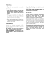
6. Start the saw. Turn the adjustment screws (F) to
tilt the idler wheel (Figure 14) until the blade is
touching the shoulder of the idler wheel.
Note: As a general rule, make the same adjustment
to the two adjustment screws on the right (F). The
single adjustment on the left is independent.
7. Next, turn the adjustment screws (F) so the
blade starts to move away from the shoulder of
the wheel – then immediately turn the
adjustment screws in the other direction so the
blade stops – then moves slowly toward the
shoulder.
Keep fingers clear of the blade
and wheel to avoid injury.
8. Turn the adjustment screws (F) to stop the
motion of the blade on the wheel as it gets
closer to the wheel shoulder.
Put a 6-inch length of paper (J, Fig. 14) between
the blade and the wheel as shown (the saw is
still turned on). The paper should not be cut as it
passes between the wheel shoulder and the
blade.
9. Turn the adjustment screws (F) slightly.
Figure 13
Figure 14