


9
2. Place a warning placard or tag on the
service panel to prevent accidental
electrical shock.
3. When installing the motor power cord into a
receptacle, make sure the plug is
compatible with the receptacle.
4. When using hard-wired connections,
connect the wires as shown in the Wiring
Data section.
5. Install the fuses or reset the breakers.
Check operation of the saw.
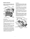
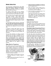
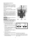
Controls and Indicators
Control Panel
The operating controls for the cut-off saw are
located on the control panel (Figure 5) and
consist of the following controls and indicators:
Coolant Pump Switch – turns the coolant pump
on and off.
Emergency Stop Switch – press to stop the drive
motor. Note: A micro switch also stops the
motor when the workpiece is cut and the saw
head is completely down.
Start Switch – press to start the drive motor. The
saw head must be in the raised position.
Power Light – indicates that machine is plugged
in and the outlet circuit breaker is turned on. The
machine does not need to be running for the
power light to be on.
Feed Rate Control – this knob is used to set the
amount of downward force that is applied to the
saw blade. The feed rate is proportional to the
opening of the valve. When set to zero, the saw
head is locked in the raised position. Increasing
the valve opening (counterclockwise adjustment)
increases the feed rate; decreasing the valve
opening (clockwise adjustment) reduces the
feed rate.
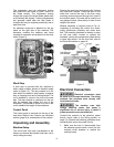
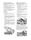
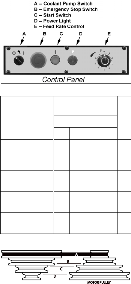
Blade Speeds
The Model 7015 horizontal cut-off bandsaw has
four blade speeds. The different speeds are
obtained by changing the position of the motor
drive V-belt on step pulleys. Change blade
speeds as follows:
1. Disconnect the electrical power from the
cut-off saw branch circuit to prevent
accidental motor start-up
2. Set the saw head at the fully down position.
3. Remove the knob from the drive belt cover.
Swing cover out and downward to expose
the V-belt and pulleys.
4. Loosen the drive motor locking handle.
Pivot the motor inward to slacken the belt.
5. Select the speed using the placard on the
cover. Put the V-belt in the pulley grooves
of the pulley for the desired speed. Refer to
Figure 6 for belt locations and the speeds
available.
Figure 5
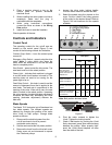
Belt Speed
60Hz 50Hz
Material to Be Cut
fpm mpm fpm mpm
Belt Position
Tool Steel, Stainless
Steel, Alloy Steel,
Phosphor Bronze, Hard
Bonze, Hard Cast Iron,
Malleable Iron
82 25 68 21
A
Mild Steel, Soft Cast Iron,
Medium Hard Brass,
Medium Hard Bronze
132 40 110 33
B
Soft Brasses and
Bronzes, Hard Aluminum,
Plastics
170 51 142 43
C
Plastics, Soft and Medium
Aluminum, Wood, Other
Light Materials
235 71 196 60
D
Note: Belt position A shown below
Figure 6
6. Pivot the motor outward to tighten the
V-belt. Tighten the locking handle.
7. Check V-belt tension by pushing the V-belt
firmly downward; press down about midway
between the pulleys. When properly tight-
ened, the V-belt should depress no more
than the width of the belt.