


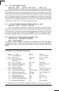
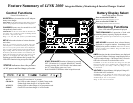
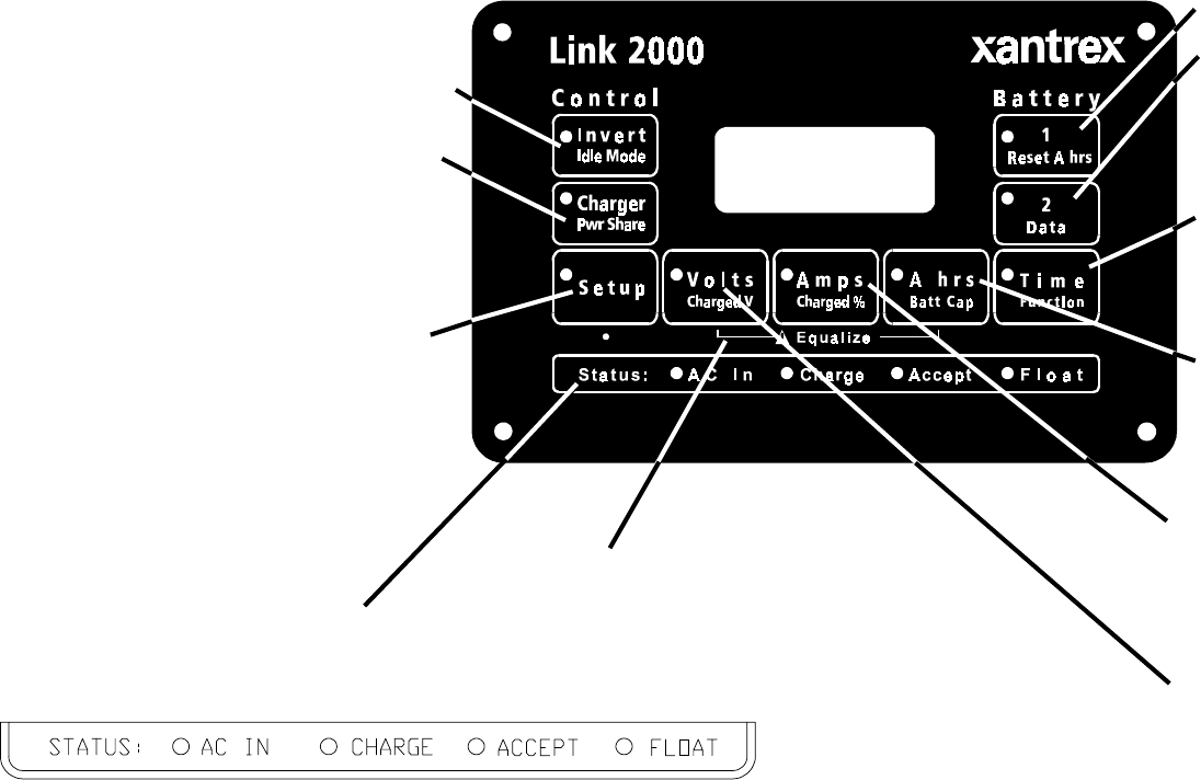
Monitoring Functions
SET UP allows the selection of various functions
and values.
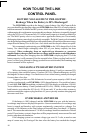
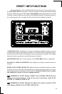
Press for 5 seconds to enter Set Up mode. The green
LED will flash at 1 second intervals. Then press the func-
tion to be set up. The present value will be displayed.
After 3 seconds, with the button pressed, the display will
begin scrolling. When the desired value appears, release
the button. If the button continues to be held down, the
display will increment to the end of its range where it will
roll over to its minimum value and contine to scroll.
Flashing green LED indicates Set Up mode. The
LED of the function being set up also flashes.
START EQUALIZE function of charger by pressing
SET UP button for 5 seconds followed by simulta-
neously pressing the VOLTS and A hrs buttons until
the "E" in the display goes out (3 sec.).
Red CHARGE LED flashes when in equalize mode.
STATUS indicators show the presence
of AC power and the charge cycle state.
AC IN: Green LED on when AC is present.
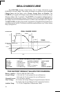
CHARGE: Red LED on when charger is in Bulk Charge mode.
Flashes Red when charger is in Equalize mode.
ACCEPT: Orange LED on when charger is in Acceptance mode.
FLOAT: Green LED on when charger is in Float mode.
Control Functions
INVERTER may be turned On or Off indepen-
dently from charger.
IDLE MODE sets the load sensitivity while idling, expressed
in Watts. Range depends on Freedom inventer being used.
CHARGER feature may be turned On or Off
independently from inverter.
PWR SHARE sets the AC current limit at which the bat-
tery charge rate is reduced to avoid overloading limited
AC sources. Expressed in Amps.
Range = 5A, 15A, 20A, 30A, (Varies by Freedom model)
Battery Display Select
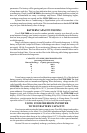
Green LED indicates on.
Green LED indicates selection.
TIME REMAINING of operation of load with
remaining battery capacity, displayed as hours.
FUNC Allows special set ups to tailor meter to your particular
application.
AMP-HOURS consumed from selected battery
displayed as a negative number. Overcharge A hrs
displayed as positive number. BATT CAP sets battery
capacity. Default value=200Ahrs. Range 20–2000 Ahrs in
20 Ahr increments.
AMPS charging into the selected battery are displayed
as a positive number. Discharge Amps displayed as a
negative number. Range + 500 Amps with 0.1A resolu-
tion below 42A and 1A resolution above 42A.
CHARGED % sets the current that the charge rate must fall
below for the battery to be considered full. Default value=2%
of battery capacity. (Ex: 4Amps = 200 x 2%). Range 1–7% in
1% increments. .
VOLTAGE of selected battery is displayed. Range 8.5–
50 Volts with 0.05V resolution.
CHARGED V sets the Voltage the battery must be above to be
considered full. Default value = 13.2V or 26.4V Sets default
automatically for 12V or 24V systems..
Range 13–32V in 0.1V increments.
Press to select BATTERY #1.
RESET A hrs of the selected battery to zero.
Green LED indicates parameter displayed.
Press to select BATTERY #2.
DATA Displays historical data about battery.
Feature Summary of LINK 2000 Integrated Battery Monitoring & Inverter/Charger Control