


975-0545-01-01 7
Freedom SW 3000 Inverter/Charger Features
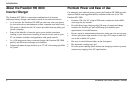
Front and Side Panels
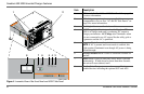
Before you begin to operate the Freedom SW 3000, review the front panel
features shown in Figure 3 and described in the next table. A detailed view
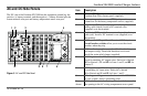
of the lights and buttons on the front panel is shown in Figure 4 and
described in the table next to it.
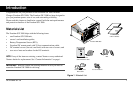
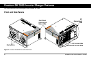
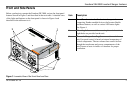
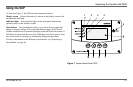
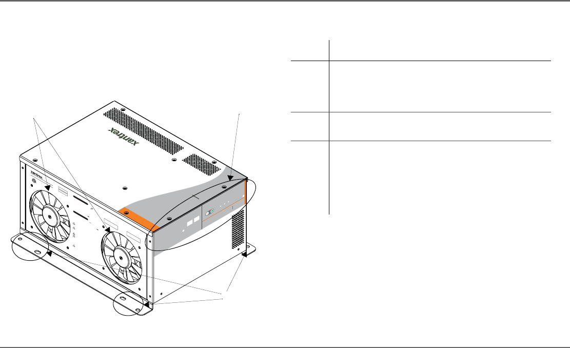
Figure 3
Isometric View of the Front Panel and Fans
FREEDOM
SW 3000
I
n
ver
t
er
R
e
set Enable
I
n
v
e
rt
er
AC/
On
C
ha
r
ge
Fault
X
anbus
I
nte
r
fa
c
e
Date
of Manufacture
Serial Number
CAUTION:
To reduce the risk of fire, do not
cover or obstruct ventilation openings. Do not mount
in a zero-clearance compartme
nt. Overheating may
result. Do not expose to rain
or spray.
INSTALLATION REQUIREMENTS:
Mount this inv
erter/charger only in the orientations
specified in the inst
allation guide provided.
WARNING:
Shock hazard. Do not open. No
user serviceable parts. Energized from both AC and
DC sources. Disconnect all sources before servicin
g.
Use only ground-fault circuit interrupters (GFCI)
specified in the installation guide supplied. Other
types may fail to operate pro
perly when connecte
d to
this equipment. Refer to manual. Charge only
lead-acid batteries. Other b
a
ttery types may burst
causing personal injury and damage.
Nominal DC Operating Voltage:
12 Vdc
Nominal AC Output Voltage:
120 Vac , 1Ø
Nominal AC Output Frequency:
60 Hz
Max. Continuous AC Output Current:
25 A
Max. Operating DC Input Current:
320 A
Max. Continuous AC Output at Nominal DC
Input: 3000 VA at 25°C
Max. Output Surge Power (5 s duration):
6000 VA
Max. DC Input Voltage:
16 Vdc
Max. Ambient Temperature:
5
0°C
Inverter Mode:
Nominal AC Input Voltage:
120 Vac , 60 Hz, 1Ø
Power Factor:
> 0.95
Charging DC Output Voltage Range:
5.0 - 16.0 Vdc
Max. Continuous Battery Charger DC Current at
Nominal AC Input:
150 A
Max. AC Input Current:
30 A per line Split Phase,
30 A per line Dual
Charger Mode:
3000W SINEWAVE INVERTER/CHARGER
FSW3000
815-3000
Model
Number
FGA
Number
FREE
DOM SW 3000
Designed in Canada
Assembled in China
DANGER:
To reduce the risk of explosion, do not
install in an area in
which igni
tion-protecte
d
euipment is requi
red.
UL 45
8
CS
A 107.1-01
3033614
FREEDOM SW 3000
2
1
3
Item Description
1 Front Panel contains the Xanbus interface ports for
connecting Xanbus-enabled devices, the Inverter Enable
and Reset buttons, as well as various LED status lights.
See Figure 4.
2 Mounting holes are used for mounting the unit. A total of
eight holes are provided on the unit.
3 Two variable-speed cooling fans are used to cool the
unit. Fan speed control is based on internal temperature of
critical components. The two exhaust fans control airflow
though the transformer and power compartments of the
unit. Ensure at least six inches of clearance for proper
ventilation.