


975-0545-01-01 9
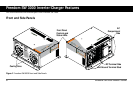
Freedom SW 3000 Inverter/Charger Features
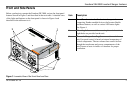
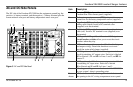
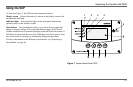
AC and DC Side Panels
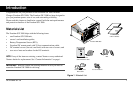
The DC side of the Freedom SW 3000 has the equipment ground lug, the
positive (+) battery terminal, and the negative (–) battery terminal plus the
remote network com port and battery temperature sensor com port.
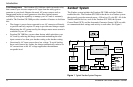
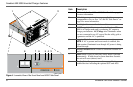
Figure 5
AC and DC Side Panel
AC INPUT
LINE 1
REM
BTS
Wiring box cover must be in place during
use to reduce risk of injury to persons
A
C INPUT
LINE 2
INVE
RTER
AC OUTPUT
AC
OUT
AC
IN
AC GROUNDS
(BEHIND COVER)
WARNING:
INCORRECT BATTERY
P
O
L
A
R
I
T
Y
W
ILL
CAUSE
D
A
M
A
G
E T
O
U
N
IT.
5
76
321
4 89
Item Description
1 Remote (REM) jack provides connection for the
Freedom Sine Wave remote panel (supplied).
2 Battery temperature sensor (BTS) jack provides
connection for the battery temperature sensor (supplied).
3 Negative (–) DC terminal connects to the negative
battery cable (black). Install a DC terminal cover
(supplied) over the terminal.
4 Positive (+) DC terminal connects to the positive battery
cable (red). Install a DC terminal cover (supplied) over
the terminal.
5 AC Input 1, AC Input 2, and Inverter AC Output
circuit breaker switches allow you to reset the circuit
breakers when they trip.
6 AC knockouts provide access for AC cables (both input
and output wiring). Detach the knockout covers and
install the strain-relief clamps (supplied).
7 AC Output terminal block is a screw-type terminal
block for attaching AC output wires. Each slot is labeled
N1 for Neutral 1, L1 and L2 for Lines 1 and 2, and N2 for
Neutral 2.
8 AC Input terminal block is a screw-type terminal block
for attaching AC input wires. Each slot is labeled
N for Neutral and L1 and L2 for Lines 1 and 2.
9 Chassis ground lug connects the chassis of the FSW3000
to your system’s chassis grounding point.
Not
shown
All Ground terminals are along the tab at the bottom of
the opening to the AC wiring compartment access panel.