


Installing the XC Series
975-0187-01-01 2–5
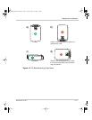
5. Install the cable strain relief on the XC Series end of the source AC cable.
6. Carefully remove 50 – 75 mm (2 – 3 in.) of the outer jacket, being careful not to
cut or nick the insulation on the individual conductors.
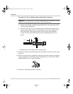
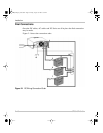
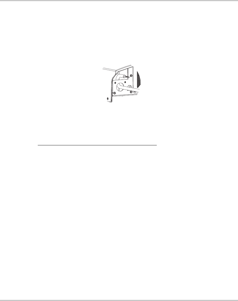
7. Pull the XC Series pigtail wires out through the access hole.
8. Thread the source AC cable through the knockout beneath the wiring
compartment cover and then pull it out through the access hole.
9. Connect the AC wiring to the XC Series pigtail wires, being sure to connect the
line conductor to the line, the neutral to the neutral, and the ground to the
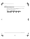
ground. The pigtail wires are color coded as follows:
10. Make the connections with twist-on or crimp-on connectors or with other
approved connectors suitable for your installation. For example, the ABYC
Standards and Recommended Practices for Small Craft prohibit twist-on
connectors for AC connections on a boat. For non-marine installations in
locations not subject to vibration, either type of connector may be used.
For marine installations, follow the procedure for installing butt splice
connectors.
Conductor Color code
Line Black or brown
Neutral White or blue
Ground Green with yellow stripe
XC_Charger_Owner.book Page 5 Friday, August 12, 2005 3:23 PM