


19
7-INSTALLATION (continued)
2011 October
700aks-NA
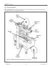
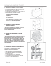
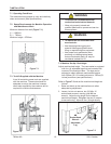
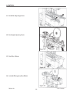
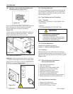
7.5 Removal of Plastic TIes
Cut the plastic which attaches the top head to the
frame and remove the polystyrene blocks (Figure 7-4).
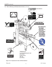
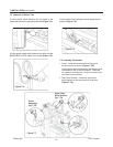
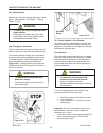
Cut the plastic strap which attaches the strip and the
EMERGENCY STOP cable to the frame
(Figure 7-5).
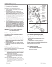
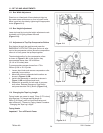
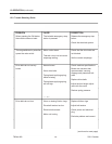
Cut the plastic ties holding the lower taping head in
position
(Figure 7-6).
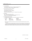
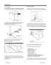
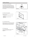
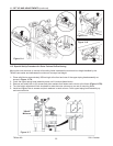
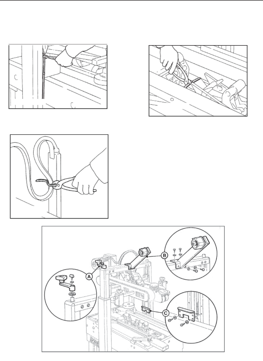
7.6 Assembly Completion
1 Crank - Install the crank handle on the top of
the left column as shown (Figure 7-7B).
Upper taping head frame height adjustment crank
is installed on top of the left column. If desired,
for operator convenience, it may be moved to the
right side of the machine.
2 Tape Drum Bracket - Install the upper tape
drum bracket on the top cross bar as shown
(Figure 7-7A).
Figure 7-5
Figure 7-7
Crank
Assembly
Fig. 7-7B
Upper Tape
Drum Bracket
Fig. 7-7A
Figure 7-6
Figure 7-4