30
d. Turn up output current to:
17.0Adc (6030A)
120Adc (6031A)
50Adc (6032A)
5.0 Adc (6035A)
e. Increase the load resistance until the output voltage between + S and - S decreases to:
60Vdc (6030A)
7.0Vdc (6031A)
20.0Vdc (6032A)
200 Vdc (6035A)
Check that the CC LED is still on.
f. Adjust autotransformer to the minimum for your line voltage.
g. Record the voltage across Rm.
h. Adjust autotransformer to the maximum for your line voltage.
i. When the reading settles record the voltage across Rm again. Check that the two recorded readings differ no more than:
6mA (6030A)
37mA (6031A)
15mA (6032A)
18 mA (6035A)
PARD Ripple And Noise. Periodic and random deviations (PARD) in the unit's output (ripple and noise) combine to
produce a residual ac current as well as an ac voltage super-imposed on the dc output. The ac voltage is measured as
constant-voltage PARD, Page 23. Constant-current PARD is specified as the root-mean-square (rms) output current in a
frequency range 20Hz to 20MHz with the unit in CC operation. To avoid incorrect measurements, with the unit in CC
operation, caused by the impedance of the electronic load at noise frequencies, use a:
3.5Ω (6030A)
0.069Ω (6031A)
0.4Ω (6032A)
40Ω (6035A)
load resistor that is capable of safely dissipating 1000 watts. Proceed as follows:
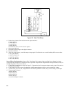
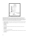
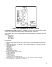
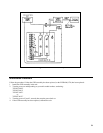
a. Connect the test equipment as shown in Figure 2-9.
Note: For Agilent 6031A units, use a 30Adc power supply in the test setup to subtract from the 120Adc of the Agilent
603lA unit under test. This will prevent the current probe specified in Table 2-1 from saturating. Make
sure the rms noise of the 30Adc supply is less than 10mA rms.
b. Switch the unit's power on and turn the output voltage all the way up.
c. Turn up output current to:
17.0Adc (6030A)
120Adc (6031A)
50 Adc (6032A)
5.0 Adc (6035A)
Check that the unit's CC LED remains lighted.
d. Check that the rms noise current measured by the current probe and rms voltmeter is no more than:
15mA rms (6030A).
120mA rms (6031A)
25mA rms (6032A)
50 mA rms (6035A)


