73
Control Board
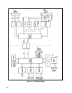
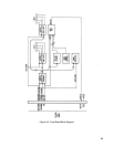
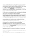
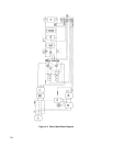
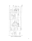
Figure 4-6 is a block diagram of the control board. These circuits monitor the power supply operation and provide the
signals that control the power mesh.
+ 5V Bias Supply. This circuit operates from the + 5V Unregulated voltage from the main board, and generates + 5V and
+ 2.5V used by circuits on the control board. Regulated + 5V is also supplied back to the main board for use by the relay
circuits, FET Drivers, and Down Programmer. The + 5V Bias Supply is regulated by a pulse width modulator chip that is
synchronized by the 40KHz clock signal to the main Pulse Width Modulator; this eliminates the possibility of frequency
modulated signals on common lines.
Bias Voltage Detector and Relay Driver. The Bias Voltage Detector monitors + 5V Unregulated to determine when bias
voltages are sufficient to ensure proper operation. After turn-on, as the output of the + 5V bias supply rises from 0Vdc
through approximately 1Vdc, three transistor switches in the Bias Voltage Detector turn on. They inhibit the relay driver
and the on-pulse driver, and generate the power-clear signal. The switches remain on until the + 5V Unregulated input
exceeds approximately 13 volts, which is sufficient to ensure both a stable + 5V output and adequate FET drive voltage.
PCLR holds various circuits reset until after the bias voltages stabilize and control circuits are certain to be working.
RELAY ENABLE , which is delayed for approximately 2 ½ seconds by the Time Delay Circuit, drives relay circuits on the
main board that short out inrush current limiting resistors after input filter capacitors are charged up. RELAY ENABLE
cannot occur until bias voltages have stabilized and time delay has expired. ON - PULSE INHIBIT shorts ON pulses to
ground whenever bias voltage is insufficient to ensure proper operation.
Note that Bias Voltage Detector inhibits power supply operation in two circumstances: while bias voltages are stabilizing
after turn-on, and when ac input drops below an adequate level (brownout).
+ 15V Bias Supply. This circuit produces the + 15V and +5.9V bias voltages. It also produces the reference voltage used
by the CC and CV Current Sources.
Time-Delay Circuit. This circuit generates the signal that delays RELAY ENABLE for approximately 2 ½ seconds after
cessation of an ac fault (Dropout or High AC). The AC FAULT signal is extended for the duration of the time delay and
supplied to: the 1.25KHz counter in the 20KHz Clock Circuit to reset the counter, so that the time delay output of the Time
Delay Circuit will remain set; the Pulse Width Modulator (PWM) to inhibit the PWM in case of an ac fault.
AC Dropout Detector. The AC Dropout Detector operates to shut down the power mesh when primary power is turned off
or lost. The circuit monitors the 120Hz signal (full-wave rectified 60 Hz ac) from the bias transformer on the main board.
Dropout is detected by a ramp circuit that is reset by the 120 Hz pulses. If the ramp is not reset within approximately 20
milliseconds of the previous reset, the circuit generates AC FAULT, which is supplied to the Time Delay Circuit to disable
RELAY ENABLE and the PWM.
High AC Detector. The High AC Detector protects the power supply from damage from ac power line surges. The circuit
contains a comparator that monitors the voltage level of the 120Hz signal. If this voltage exceeds a safe operating level, the
circuit generates the
HIGH AC signal, which is ORED with AC DROPOUT . Either can cause generation of the AC
FAULT signal.
Turn-On Overshoot Control. The Turn-On Overshoot Control Circuit prevents output overshoot when the Pulse Width
Modulator is turned back on after having been turned off. The circuit monitors the
PWM OFF signal from the Pulse Width
Modulator. If the PWM is turned off because of INHIBIT (from GPIB), AC FAULT , OT (overtemperature), or OV
(overvoltage), the power supply output will be down programmed to zero, and both the CC and CV Circuit outputs will
increase to maximum in an attempt to restore the output level. This circuit holds the CONTROL PORT at a low level to
prevent output overshoot when
PWM OFF is removed.


