


10
G-Converter Chassis
SALES: 0118 965 5100
Installation
Before installation, refer to the safety warnings, approvals requirements and emc
requirements in the appendices.
Environmental Considerations
The equipment must be operated under the following atmospheric conditions:
Temperature: 0 to 40 degrees centigrade.
Humidity: 0% to 90% non-condensing.
Card Cage System
The Card Cage System should be housed in a cabinet that is considered by EN60950 to be a
suitable electrical and fire enclosure. Refer to Appendix A for safety warnings. A fixing
flange is fitted to the front of the Card Cage to mount the unit into the cabinet.
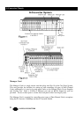
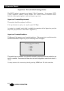
Manager Card
Note: THE MANAGER CARD MUST ONLY BE PLUGGED INTO SLOT 19.
The Manager Card is connected to the 9 Way-D Supervisor Port, and the RJ45 10Base-T
port, located adjacent to the fan on the rear of the Card Cage. Connection between individual
Channel Cards and the Manager Card is achieved via the back plane (See Figures 1 and 2).
There are no user configurable links on the Manager Card.
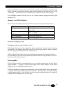
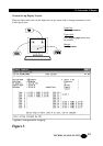
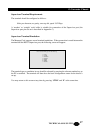
Power Supplies
The Power Supplies are installed in Slots 20 and 21. Slot 21 is located on the extreme right
hand side of the Card Cage, when viewing it from the front, (See Figure 1). Mains power for
Slots 20 and 21 is provided by a pair of IEC connectors, the upper connector is allocated for
Slot 21, the lower connector for Slot 20.
When only one Power Supply is fitted it should be into Slot 21 with mains power being
supplied via the upper IEC connector. A blanking panel should be installed to cover Slot 20.
Channel Cards
Channel Cards for the Card Cage may be selected to meet several requirements; the cards are
fitted into slots 1 to 18. The cards can be ‘hot swapped’ by simply releasing the retaining
screws on the top and bottom of the panel and with the aid of the injector/ejector handles
carefully withdrawing the card. Simply reverse this process to install a card.