


!& V
06A?@5:3@413A->053
!;@1 The guard is pre-adjusted to the diameter of the gear
case hub at the factory. If, after a period of time, the guard
becomes loose, tighten the adjusting screw with latch in
the closed position and guard installed on the tool.
-A@5;: Do not tighten the adjusting screw with the
latch in the open position. Undetectable damage to the
guard or the mounting hub may result.
-A@5;: If the guard cannot be tightened by the guard
latch, do not use the tool and take the tool and guard to a
service center to repair or replace the guard.
"#%'"!
&C5@/4
To start the grinder, push the slider switch forward. For
continuous operation, push the slider switch forward and
push the front down until it locates in the lock position. To
turn the tool off, press the rear of the slider switch. Spring
action returns the switch to the off position.
-A@5;: Hold the side handle and body of the tool
firmly to maintain control of the tool at start up and during
use and until the wheel or accessory stops rotating. Make
sure the wheel has come to a complete stop be fore laying
the tool down.
-A@5;: Allow the tool to reach full speed before
touching tool to the work surface.
Lift the tool from the work surface before turning the tool off.
&<5:0818;/7
The spindle lock button is provided to prevent the
spindle from rotating when installing or removing wheels.
Operate the spindle lock only when the tool is turned off and
the wheel has come to a complete stop.
*->:5:3 Do not engage the spindle lock while the tool
is operating. Damage to the tool will result and attached
accessory may spin off possibly resulting in injury.
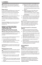
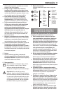
';1:3-31@418;/7 depress the spindle lock button shown
in 53 and rotate the spindle until you are unable to
rotate the spindle further.
"(!'!!(&!#%&&!'%
%!!*&!&!!#&&
;A:@5:3-:0%19;B5:3A..10*4118?
*->:5:3 ';<>1B1:@-//501:@-8;<1>-@5;:@A>:;22
-:0A:<8A3@;;8.12;>1<1>2;>95:3@412;88;C5:3
;<1>-@5;:? Failure to do this could result in serious
personal injury.
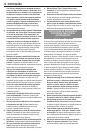
Hubbed wheels install directly on the 5/8 in.-11 threaded
spindle.
Thread the wheel on the spindle by hand.
Depress the spindle lock button and use a wrench
53 to tighten the hub of the wheel.
Reverse the above procedure to remove the wheel.
-A@5;: Failure to properly seat the wheel before
turning the tool on may result in damage to the tool or the
wheel.
;A:@5:3!;:A..10C4118?
*->:5:3To prevent accidental operation, turn off and
unplug tool before performing the following operations.
Failure to do this could result in serious personal injury.
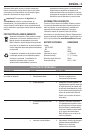
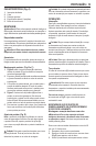
53A>1 Install the unthreaded backing flange on
spindle with the raised section (pilot) against the
wheel.
Place wheel against the backing flange, centering the
wheel on the raised section (pilot) of the backing flange.
53A>1 While depressing the spindle lock button,
thread the threaded clamp nut on spindle.
► 53A>1 If the wheel you are installing is more
than 1/8 inch (3mm) thick, place the threaded
clamp nut on the spindle so that the raised section
(pilot) fits into the center of the wheel.
► 53A>1 If the wheel you are installing is 1/8 inch
(3mm) thick or less, place the threaded clamp nut
on the spindle so that the raised section (pilot) is
not against the wheel.
While depressing the spindle lock button tighten the
threaded clamp nut with included wrench.
To remove the wheel, depress the spindle lock button
and loosen the threaded clamp nut with included wrench.
!;@1 If the wheel spins after the threaded clamp nut is
tightened, check the orientation of the threaded clamp nut.
If a thin wheel is installed with the pilot on the clamp nut
against the wheel, it will spin because the height of the pilot
prevents the clamp nut from holding the wheel.
&A>2-/13>5:05:3C5@43>5:05:3C4118?
Allow the tool to reach full speed before touching the
tool to the work surface.
Apply minimum pressure to the work surface, allowing
the tool to operate at high speed. Grinding rate is
greatest when the tool operates at high speed.
53A>1 Maintain a 20˚ to 30˚ angle between the tool
and work surface.
Continuously move the tool in a forward and back
motion to avoid creating gouges in the work surface.
Remove the tool from work surface before turning tool
off. Allow the tool to stop rotating before laying it down.