


-13-
Disconnect plug from power
source before performing any as-
sembly, adjustment or repair to avoid possible injury.
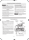
NOTE: Your miter saw was completely adjusted at
the factory. However, during shipment, slight mis-
alignment may have occurred. Check the following
settings and adjust if necessary prior to using this
miter saw.
742:8=6J4E4;39DBC<4=C
1. Push head assembly down and push head as-
sembly lock pin to hold down head assembly.
2. Slide head assembly completely to the back and
tighten the rail lock knob.
3. Rotate table to 0° miter position
4. Pull up bevel lock lever to loosen.
5. Check position of bevel range selector knob, it
should be at the 0°-45° position.
6. Tilt the saw assembly to the left counterclockwise.
Then rotate saw assembly to the right (clockwise).
Until you feel the stop in the vertical position –
This is where the saw is currently set for the 0°
bevel cut.
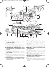
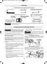
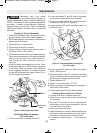
Lower the blade and engage the lock pin. Use a
combination square to check blade squareness
to the table. Place the square on the table and
press it against the blade. If the blade does not
contact the full length of the square, (figure 5), fol-
low the alignment procedure.
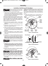
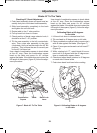
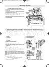
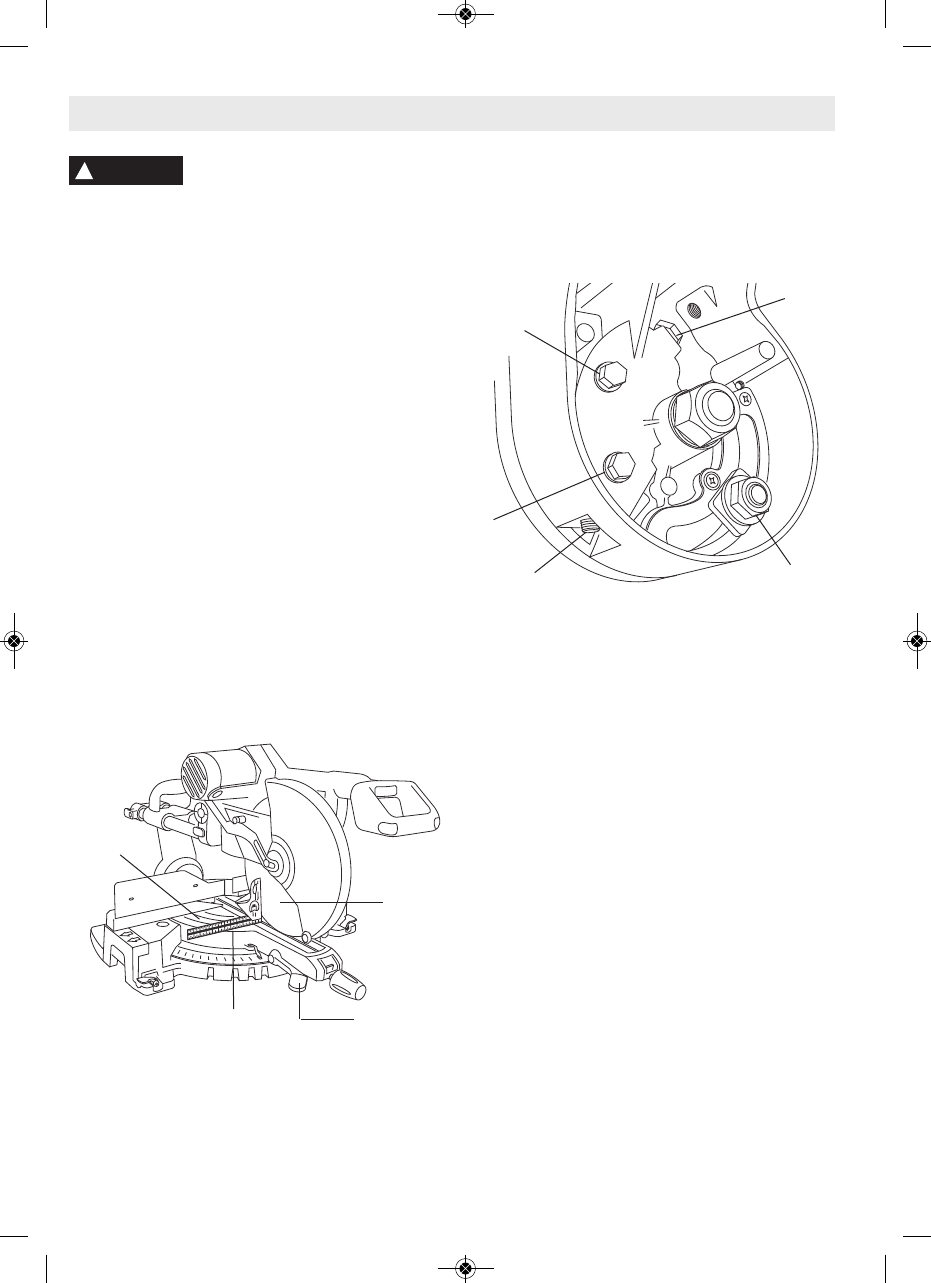
0;81A0C8=6;0340C346A44B
JC>C74C01;4
1. Lift bevel lock lever to release bevel lock.
2. Loosen bolt heads “A” and “B” with 10 mm open-
end wrench at least one full turn (Figure 6).
3. Place 4 mm Allen wrench bit onto multi purpose
tool and into setscrew “D” (Figure 6).
4. Loosen setscrew “D” with 4 mm Allen wrench - at
least 3 full turns.
5. Place combination square on table and against
fence. (See figure 5)
6. While rotating bolt head “C”, watch the saw blade
tilt until it is aligned with the combination square.
When aligned, remove the Allen wrench.
7. Tighten setscrew “D”.
8. Tighten 10 mm bolt heads “A” & “B”
9. Check and adjust bevel pointers to 0 degrees on
each side of bevel scale.
10. Push down bevel lock lever before cutting.
39DBC8=64E4;!>2:!4E4A)4=B8>=
1. Lift bevel lock lever to release bevel lock.
2. Place 17-mm open-end flat wrench on bolt head
“E” (Figure 6).
3. Turn nut “E” clockwise 1/8 turn to tighten bevel
lock tension or turn counter-clockwise to 1/8 turn
to loosen bevel lock tension.
4. Push down bevel lock lever.
5. Verify that bevel lock tension holds the bevel po-
sition secure and also allows bevel lock lever to
lock down to the point that a solid stop is felt.
6. If necessary, repeat steps 1 – 5 to adjust the
tension.
39DBC<4=CB
!
WARNING
)01;4
;034
><18=0C8>=
(@D0A4
4E4;!>2:
!4E4A
86DA4;034(@D0A4C>)01;4
86DA40;81A0C8=6;0340C346A44B
C>C74C01;4
2610009642 10/09 E:2610009642 10/09 E 10/20/09 3:17 PM Page 13