


-25-
4E4;'0=64J!45CC>J
This left side bevel range is the default setting
)>>?4A0C48=A0=64
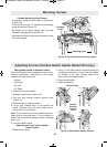
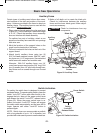
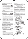
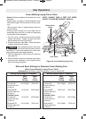
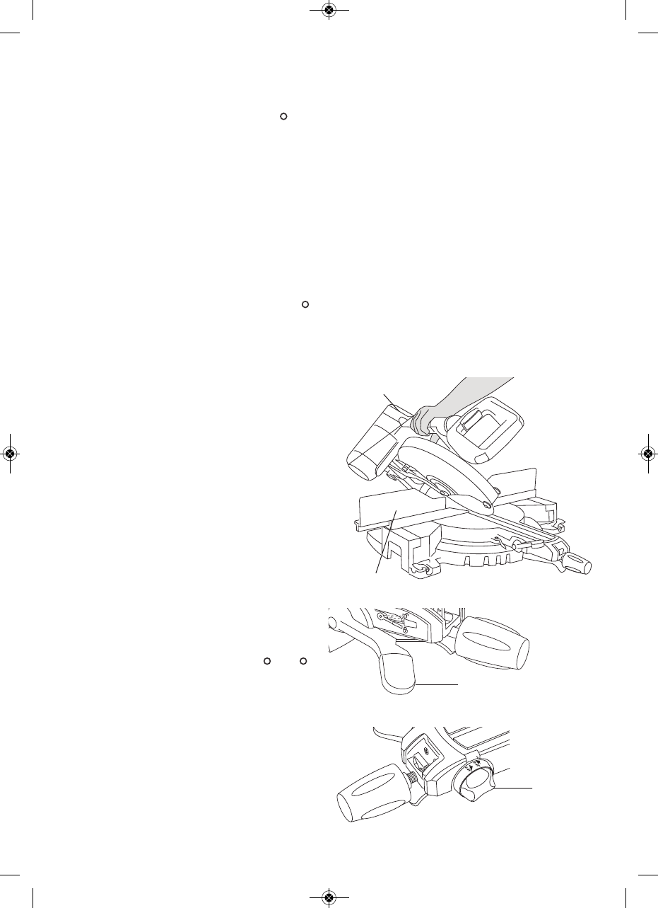
1. Move the left sliding fence to clear
saw assembly and re-lock (Figure 29).
2. Lift bevel lock lever to the table height
with the left hand (Figure 30).
3. Grasp the front carry handle with the right hand
and tilt saw head to angle desired.
4. Once in the desired bevel position, fully press
down bevel lock lever below table height
(Figure 29)..
Without turning the saw on, practice the cutting ac-
tion to make sure the fence clears the guards and
adjust as necessary.
4E4;'0=64JC>J'867C
)>>?4A0C48=A0=64
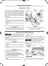
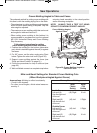
1. Move right sliding fence to clear
saw assembly and re-lock (Figure
29).
2. Lift bevel lock lever to the table height with the left
hand (Figure 30).
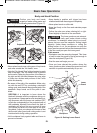
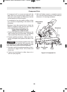
3. Grasp the front carry handle with the left hand and
tilt saw head slightly to the left while rotating the
spring-loaded bevel range selector knob with the
right hand so the symbol “ 45-0° “ lines up with
the arrow on the table (Figure 31). The saw as-
sembly may now be tilted to a right bevel angle
up to the 45° stop.
4. Once in the desired bevel position press down
bevel lock lever below table height.
NOTE: When the saw assembly is tilted back left
past 0°, the bevel control knob will snap back to the
default bevel range 1. This is designed to regain the
pre-set bevel stop at the important 0° position.
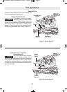
4E4;'0=64J!45CC>J'867C
This full capacity bevel range setting overrides all
preset stops and allows for cutting at bevel angles
beyond the normal 45° on either side.
)>>?4A0C48=A0=64
1. Move left and right-sliding fences
to clear saw assembly and re-lock
(Figure 29).
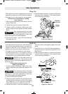
2. Lift bevel lock lever to the table height with the left
hand (Figure 30).
3. Grasp the front carry handle with the left hand and
tilt saw head slightly to the left while rotating the
spring-loaded bevel range selector knob with the
right hand so the symbol “ 47-47° “ lines up with
the arrow on the table (Figure 31). The saw as-
sembly may now be tilted to any angle from 47°
left to 47°right.
4. Once in the desired bevel position, fully press
down bevel lock lever below table height.
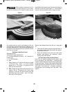
>;;>FC74B48=BCAD2C8>=B5>A
<0:8=6H>DA14E4;2DC
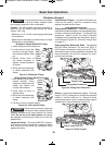
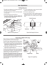
5. Extend the base extensions and fence on the side
on which the cut will be made. (See Sliding Fence
and Base Extension on page 22).
6. Properly position workpiece. Make sure work
piece is clamped firmly against the table and the
fence.
Use clamping position that does not interfere with
operation. Before switching on, lower head assem-
bly to make sure clamp clears guard and head as-
sembly.
7. Follow the procedures for either a chop cut or
slide cut (see page 23).
8. Wait until blade comes to a complete stop before
returning head assembly to the raised position
and/or removing workpiece.
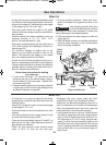
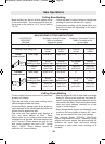
00 44-- 55
Right
44 --77 4477
Max
00
44 --55
Left
UNLOCK
LOCK
4E4;!>2:!4E4A
4E4;
'0=64
(4;42C>A
=>1
(;838=64=24
A>=C0AAH0=3;4
86DA4
86DA4
86DA4
2610009642 10/09 E:2610009642 10/09 E 10/20/09 3:18 PM Page 25