


10
stArtInG tHe ComPressor
1. Position compressor on a at surface or one with
an inclination of 10° or less, in a well ventilated
area away from vapors.
2. Ensure all covers and labels are in place, legible
(for labels) and securely mounted. Do not use
compressor until all items have been veried.
3. Ensure the power switch is in the OFF position.
4. Plug the power cord into the correct branch circuit
receptacle. See the “Grounding Section” for more
information on the correct receptacle.
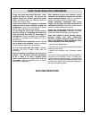
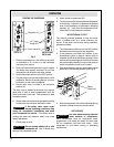
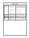
5. Ensure drain valve is closed in the horizontal
position (A).
The drain valve is located at the base of the control
panel and is used to drain condensation from the
tanks at the end of each use. Tank pressure is used
to expel the water.
6. Ensure safety valve is functioning properly by pulling
on the valve ring and allow the valve to reset.
WARNING
If the safety valve vents under
normal operating conditions, stop
using the compressor immediately and send
your compressor for service. If the safety valve is
venting the tanks the pressure switch may need
factory adjustment.
7. Check pump oil level.
CAUTION
Do not operate without oil or with
inadequate oil. Low oil levels may
damage the compressor pump.
8. Attach hoses to compressor (B).
9. Turn the power to ON, and verify that the compressor
is functioning. Adjust the air pressure the desired
level for the accessory as described in adjusting
regulator (C). Verify that the compressor motor
stops when cut out pressure is reached.
motor tHermAl Cut out
The thermal protector operates to stop the motor
when a problem such as a motor overload, etc.
occurs. If the motor should stop during operation,
proceed as follows:
1. Turn the pressure switch lever to the OFF position
and disconnect the plug from the receptacle.
2. If the extension cord does not conform to the
specications given on page 9, replace with an
extension cord such as that shown on page 9. If the
capacity of the power supply is insufcient, increase
the power supply capacity to remove the cause of
a ow of excessive current (over-current).
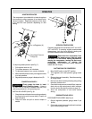
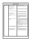
3. Wait approximately 5 minutes, then press the reset
switch (A) of the thermal protector (see Fig. 6).
4. Start the compressor. If the motor still stops during
operation, please contact the service center.
Hot surfACes
WARNING
Use care when touching exposed
metal surfaces of compressor.
Many components such as compressor head,
engine/motor, and tubing will remain hot even after
the air compressor has been shut down. Allow
compressor to cool before moving or attempting
maintenance.
oPerAtIon
Reset
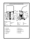
Switch (A)
Fig. 6
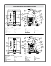
Fig. 5
Drain Valve (A)
Regulator (C)
1/4” Outlet
fittings (B)
CET3-10 CET4-20 and
CET4-20W