


8
Assembly / InstAllAtIon
lubrICAtIon And oIl
Do not attempt to operate this air
compressor without first verifying
the oil level in the crankcase. This compressor is
shipped with oil in the crankcase. Serious damage
of the compressor can result from even momentary
operation without proper lubrication.
Prior to each use, verify the crankcase oil level. An
oil sight gauge with minimum and maximum oil level
marks is provided with this compressor.
Always verify that the oil level is at the maximum
mark in the oil sight gauge before operating this
unit. Do not operate the pump with an inadequate or
excessive amount of oil. The cost of failures which
occur due to incorrect oil levels will not be covered
under warranty.
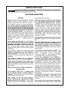
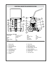
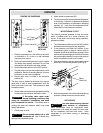
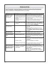
To check the oil level: (see Fig. 1)
1. Place unit on a level surface.
2. Remove dipstick, wipe with a clean rag, replace
in crankcase, then remove dipstick to inspect oil
level.
3. If oil level is low, add as required, but do not exceed
maximum oil level.
CAUTION
Do not allow particulates such as
sawdust to fall into crank case when
crank case is open for inspection. Particulates in oil
may reduce compressor life.
CAUTION
Do not use a detergent oil in
crankcase. Detergent oils will leave
deposits on internal compressor components
reducing compressor life and performance.
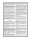
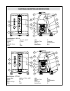
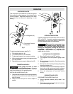
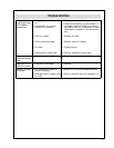
dIreCtIons for InstAllInG WHeels
(Cet4-20W only See Fig. 2)
1. Take wheel spindle (A) and thread into wheel
bracket (B), which is welded to compressor frame.
Tighten spindle with wrench to secure to frame.
2. Slide wheel onto wheel spindle. Ination stem for
wheel assembly should face toward the compressor
frame.
3. Place screw through washer (D) and thread screw
into end of wheel spindle (C). Tighten screw to
secure to spindle.
4. Repeat these steps for second wheel.
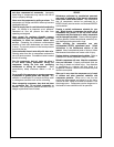
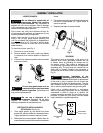
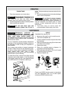
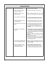
GroundInG
This product must be grounded. In the event of an
electrical short circuit, grounding reduces the risk
of electric shock by providing an escape wire for
the electric current. This product is equipped with
a cord having a grounding wire with an appropriate
grounding plug. The plug must be inserted into an
outlet that is properly installed and grounded in
accordance with all local codes and ordinances (see
Fig. 3).
WARNING
Improper installation of the
grounding plug is able to result in
a risk of electric shock. When repair or replacement
of the cord or plug is required, do not connect the
grounding wire to either flat blade terminal. The wire
with insulation having an outer surface that is green
with or without yellow stripes is the grounding wire.
Check with a qualied electrician or serviceman
when the grounding instructions are not completely
understood, or when in doubt as to whether the
product is properly grounded. Do not modify the plug
provided; if it does not t the outlet, have the proper
outlet installed by a qualied electrician.
CAUTION
Fig. 1
MAX
MIN
Fig. 2
(A)
(B)
(D)
(C)
GROUNDING
PIN
GROUNDED
OUTLET
GROUNDED
OUTLET BOX
Fig. 3