


9
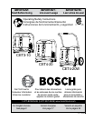
This product is for use on a nominal 120-V circuit and
has a grounding plug similar to the plug illustrated on
page 8. Only connect the product to an outlet having
the same conguration as the plug. Do not use an
adapter with this product.
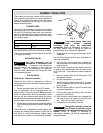
extensIon Cords
Use only a 3-wire extension cord that has a 3-blade
grounding plug, and a 3-slot receptacle that accepts
the plug on the product. Make sure your extension
cord is not damaged. When using an extension cord,
be sure to use one heavy enough to carry the current
your product draws.
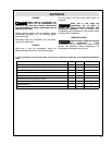
RECOMMENDED SIZES OF EXTENSION CORDS
The maximum recommend cord length is 50 feet with
a 12 gauge cord rating.
PrePArAtIon for use
WARNING
Use this compressor and all
accessories in accordance with
the instructions. Compressor and accessories
must be used for the purpose for which they are
designed. Use of the compressor for operations
other than what is described in this manual can result
in a hazardous situation.
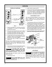
eleCtrIC motor
Initial Set-Up – Break-in Procedure
Before rst use of this air compressor or after the
compressor pump/motor has been replaced, perform
the following:
1. Ensure the power switch is in the OFF position.
This air compressor has an integrated power and
pressure switch. When the power is ON the pressure
switch will automatically start the compressor motor
any time the tank pressure drops below the factory
set cut-in pressure and stop the motor when the tank
pressure stops at the factory set cut-out pressure.
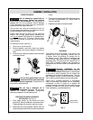
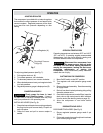
2. Ensure safety valve is functioning properly by pulling
on the valve ring and allow the valve to reset (see
Fig. 4).
The safety valve is designed to protect against high
pressure by releasing high pressure air from the air
tank when its factory set pressure (slightly higher
than the pressure switch cut-out setting) is exceeded.
WARNING
If the safety release valve vents
under normal operating
conditions, stop using the compressor
immediately. Send your compressor for service. If
the safety release valve is venting the tanks the
pressure switch may need factory adjustment.
3. Plug the power cord into the correct branch circuit
receptacle.
See the “Grounding Section” for more information on
the correct receptacle.
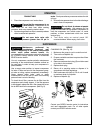
4. Open the drain valve to permit air to escape the
tank and prevent air pressure build up during the
break-in period.
The drain valve is located on the control panel and
is used to drain condensation from the tanks at the
end of each use. Tank pressure is used to expel the
water.
5. Move the power switch to the ON position. The
compressor will start.
6. Run the compressor for 20 minutes.
7. After 20 minutes, close the drain valve. The tank
will ll to cut-out pressure and the compressor
motor will stop.
8. Move the power switch to the OFF position and
unplug the compressor.
9. Pull the safety valve and allow to vent until tank
pressure is under 20 psi.
10. Open the drain valve to permit air to escape the
tank and to drain any moisture or particles from
tank. When tank is empty, close drain.
11. Compressor is now ready for rst use.
CAUTION
Change the crankcase oil after the
first 50 hours of operation and as
recommended in the maintenance section of this
manual. Failure to change oil according to
maintenance schedule will reduce compressor life
and performance.
Assembly / InstAllAtIon
Extension Cord Table
0 – 25 ft 25 – 50 ft.
14 ga. 12 ga.
Fig. 4