


10
Operating Instructions and Parts Manual
Airless Paint Systems
www.chpower.com
Service
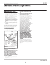
FLUID PUMP
FLUID PUMP DISCONNECT
1. Flush out the material you are
spraying, if possible.
2. Follow the Pressure Relief
Procedure on page 3. Stop the
pump in the middle of down stroke.
3. Remove the suction tube and fluid
hose (if so equipped) from the fluid
pump. Detach the hose from the
front of the fluid pump.
4. Remove 2 retaining rings and slip
the sleeve of the coupling down
and remove both coupling halves.
This will disconnect fluid pump
from the connecting rod.
5. Unscrew the two tie rod locknuts.
6. Pull the pump down off the tie
rods.
FLUID PUMP REINSTALL
1. Loosen packing nut and extend
piston rod so that it is in the “fully
up” position.
2. Make sure that spacer tubes (301-
048) are in place.
3. Connect connecting rod with fluid
pump by installing coupling halves.
Slide sleeve over coupling halves.
Secure with retaining rings.
4. Secure the fluid pump housing to
the tie rods and screw nuts with
lock washers on loosely.
5. Tighten the tie rod nuts evenly to
30 ft. lb.
6. Reconnect fluid hoses and suction
tube (if so equipped).
NOTE: After all the rod locknuts are
tight, the alignment of both rods
should allow easy assembly and
disassembly of the coupling. If there is
any binding, loosen and retighten all
the rod locknuts to improve the
alignment. Misalignment causes
premature wear of seal and packings.
7. Tighten the packing nut until there
is resistance, then tighten it 1 full
turn. Approximately 4 threads will
show when new packings are
installed. Fill the wet cup of the
packing nut 1/3 full with Throat
Seal Oil.
8. Start the pump and operate it
slowly (at low engine speed and
pressure setting ) to check the
piston rod for binding.
Adjust tie rod lock nuts if necessary
to eliminate binding.
9. Run at maximum pressure for
several minutes, relieve pressure
and repeat step 7.
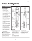
AL2810
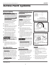
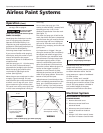
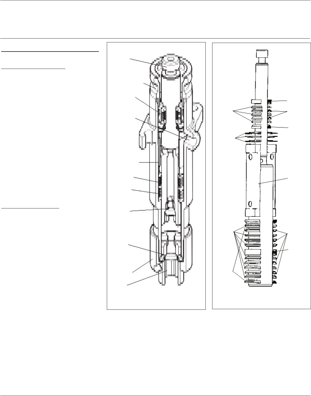
Figure 9 - Inlet Valve, Outlet Valve,
Piston Assembly
Piston
Packing nut/
wet cup
Upper
packing
Fluid
outlet
Distance
tube
Lower
packing
Wiper
packing
Outlet
valve
Inlet
valve
Suction
nut
Fluid
inlet
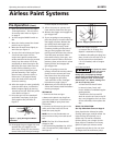
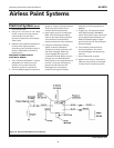
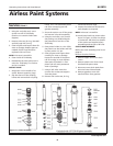
Figure 10 - Piston Assembly
187-030
187-031
187-029
187-037
187-026
187-060
187-025
187-315
187-059
187-058