


9
Airless Paint Systems
Operating Instructions and Parts Manual
www.chpower.com
Electrical System (Cont.)
and remove knob.
5. Using a 1/2” nut driver or 1/2” deep
socket, remove nut from pressure
control shaft. This will allow
removal of electrical control board
from frame.
6. Replace electrical board assembly in
reverse order. Adjust pressure
according to the procedure given in
Pressure Calibration on Electrical
Board section.
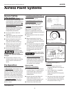
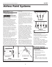
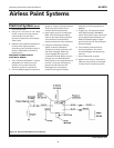
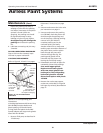
PRESSURE CALIBRATION ON
ELECTRICAL BOARD
1. Turn "Pressure Calibration" Trimpot
adjustment on electrical control
board in the counter clockwise
direction at least 15 revolutions.
2. Connect 5000 psi glycerine pressure
guage on output of pump between
fluid pump and airless hose to
monitor Fluid Pump Pressure.
3. Start engine and run at maximum
RPM. Turn Prime/Pressure Relief
Valve to the open (Prime) position.
Turn Pressure Control Knob to
maximum position (fully clockwise).
4. Using an insulated screwdriver,
adjust "Pressure Calibration"
Trimpot by turning clockwise until
the clutch engages. When the
clutch engages the pump will
commence Priming. When pump is
primed, turn the Prime/Pressure
Relief Valve to the Closed (Pressure)
position. The pump will begin to
pressurize and the clutch will
disengage at a low pressure.
Continue turning the Trimpot
clockwise to increase pressure to
3000 psi.
5. Trigger gun. The pressure should
drop approximately 350-400 psi
(when using a 3/8" hose), the clutch
will engage and build pressure to
3000 psi and disengage. Trigger
gun several times to ensure proper
pressure setting.
6. Turn Pressure Control Knob to
minimum position. The clutch
should disengage and pump stop
moving.
7. Secure leads with tie strap.
8. Replace cover on unit. Ensure the
leads are not pinched or damaged
in the process of replacing covers.
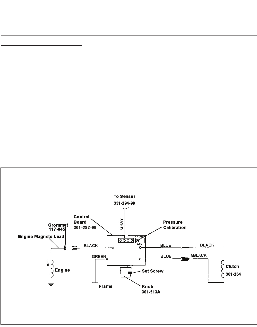
AL2810
Figure 8 - Electrical Board/Pressure Calibration