


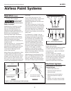
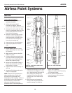
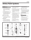

Operating Instructions and Parts Manual
16
www.chpower.com
AL2810
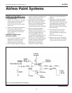
STEP 1: Ensure that the pressure control knob is in the maximum (fully clockwise) position.
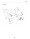
STEP 2: Remove the upper and lower clutch and electrical covers.
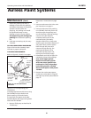
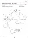
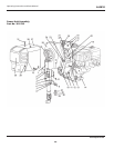
STEP 3: Check all electrical connections between the engine magneto, sensor, control board and clutch for loose connections
or damaged leads. See Figure 8 on page 9.
STEP 4: Disconnect the two leads from the control board (blue) and the clutch assembly (black). Using a multimeter, with
the engine at maximum RPM, pressure control knob in the maximum position and the prime valve open (priming) position,
test the DC voltage across the boards leads (blue). This voltage must be 13-14 VDC. If the readings are correct, the board,
sensor and magneto are okay and the problem is the clutch assembly. If this is the case, proceed to Step 5. If the voltage is
outside this range go to Step 7.
STEP 5: Measure resistance between the clutch leads (black). This value must be 10-16 ohms. If this reading is out of
specifications the clutch is defective and must be replaced, otherwise continue troubleshooting.
STEP 6: If the clutch resistance readings of Step 5 are correct, check the spacing between the clutch field and plate. The gap
must be approximately .028". If this gap is too wide, remove the spacer from the clutch assembly. Should the clutch still not
engage, replace the clutch assembly. See page 11.
STEP 7: When the DC voltage from the board is not 13-14 VDC, disconnect the control board lead (black) from the engine
magneto lead (pink), located on the side of the engine. With the engine at maximum RPM, pressure control knob in
maximum (fully clockwise) position and prime valve open (priming), read the AC voltage from the magneto lead to the
sprayer frame. This reading should be 11-30 VAC. If outside this range, contact your local Honda repair facility for magneto
replacement. If the magneto is producing the proper AC voltage, continue to Step 8.
STEP 8: Test the sensor by reading the resistance between the red and black wires. The resistance runs between 1.8-3.5
kohms. A defective sensor usually shows no resistance (open). If the reading is outside standards, replace the sensor. An
alternative method to test the sensor, is to plug a new sensor into the board and see if the clutch will engage. Caution!
When using this method, ensure prime/pressure valve is in the prime position. This is important because the sensor plugged
into the board is not measuring pressure in the fluid section.
STEP 9: When Steps 7 and 8 have been completed and the magneto and sensor check good, the electrical control board is
the only item left, replace the board. See page 8.
Steps to Follow if Clutch Does Not Engage
Troubleshooting Chart Part III - Clutch Does Not Engage