


3
Operation
Read this manual and understand all
safety warnings and instructions before
operating the nailer.
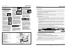
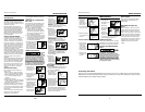
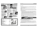
LUBRICATION
This nailer requires lubrication before
using the nailer for the first time and
before each use. If an inline oiler is
used, manual lubrication through the
air inlet is not required on a daily basis.
The work
surface
can become damaged by excessive
lubrication. Proper lubrication is the
owner’s responsibil- ity. Failure to
lubricate the nailer properly will dra-
matically shorten the life of the nailer
and void your warranty.
1. Disconnect
the air supply
from the nail-
er to add
lubricant.
2. Turn the nailer
so the air inlet
is facing up.
Place 4-5 drops
of 30 W non-
detergent oil into air inlet. Do not
use detergent oils, oil additives, or
air tool oils. Air tool oils contain sol-
vents which will damage the nailer's
internal components.
3. After adding oil,
run nailer briefly.
Wipe off any
excess oil from
the cap exhaust.
Always
know the
operational mode of the nailer before
using. Failure to know the operational
mode could result in death or serious
personal injury.
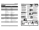
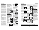
This nailer may be operated in the
“Single Cycle” or the “Bottom Trip”
mode. The nailer is delivered in the sin-
gle cycle mode. A separate ‘red’ trigger
for “Bottom Trip” mode is included
with tool as an accessory.
SINGLE CYCLE MODE
When the black trigger is installed, nail-
er is in single cycle mode. This method
is recommended when precise nail
placement is required. Operation in this
mode requires trigger to be pulled each
time a nail is driven. Nailer can be actu-
ated by depressing the Work Contact
Element (WCE) against work surface
followed by pulling the trigger.
The trigger must be released after each
fastener is driven to allow tool to reset.
Since the tool can only be actuated by
first removing the finger from the trig-
ger, this is considered to be a more
restrictive mode of operation, suitable
for less experienced users.
BOTTOM TRIP MODE
When the red trigger is installed, the
nailer is in bottom trip mode. This
method is recommended when less
precise nail placement is required.
Operation in this mode requires trigger
to be depressed with nailer off of the
work surface. Then, the nose of the
nailer is tapped against the work sur-
face causing a nail to be driven.
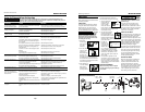
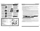
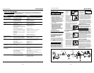
RECOMMENDED HOOKUP
The illustration below shows the
recommended hookup for the nailer.
1. The air compressor
must be able to
maintain a mini-
mum of 70 PSI
when the nailer is
being used. An inadequate air sup-
ply can cause a loss of power and
inconsistent driving.
2. An oiler can be used to
provide oil circulation
through the nailer. A fil-
ter can be used to remove
liquid and solid impurities
which can rust or “gum up” internal
parts of the nailer.
3. Use 3/8” air
hoses with a
minimum work-
ing pressure of
200 psi. Use 1/2” air hoses for 50’
run or longer. For better perfor-
mance, install a 3/8” quick plug
(1/4” NPT threads) with an inside
diameter of .315” (8mm) on the
nailer and a 3/8” quick coupler on
the air hose.
4. Use a pressure regulator on the
compressor, with an operating pres-
sure of 0 - 125 PSI. A pressure regu-
lator is required to control the oper-
ating pressure of the nailer between
70 and 120 psi.
Operational Modes
Note: This framing nailer is shipped
with the BLACK single cycle mode trig-
ger installed.
Model RN164500
Operating Instructions
70 PSI
Min.
OIL DAILY
Oxygen
Oxygen
Nitrogen
Nitrogen
Hydrogen
Hydrogen
Carbon Dioxide
Carbon Dioxide
OIL DAILY
O
xy
ge
n
N
itr
oge
n
Hyd
r
o
ge
n
Ca
r
b
o
n
Dio
x
ide
OIL
120 PSI
Max.
OIL DAILY
Oxygen
O
xygen
Nitrogen
Nitrogen
Hydrogen
Hydrogen
Carbon Dioxide
Carbon Diox
ide
Hay una fuga de aire en el
área de la válvula del gatillo
Hay una fuga de aire entre la
cubierta y la boquilla
Hay una fuga de aire entre la
cubierta y la tapa
La clavadora deja de clavar un
clavo
La clavadora funciona lenta-
mente o pierde su potencia
Hay clavos atascados en la
clavadora
Hay una fuga de aire en el
vástago de la válvula del gatillo
El clavador omite clavar un
clavo o no alimenta los clavos
adecuadamente
Los clavos están bloqueados en
el cargador
Los anillos en O de la cubierta de la válvula del
gatillo están dañados
Los tornillos de la cubierta están flojos
Los anillos en O están dañados
La defensa está dañada
Los tornillos están flojos
El empaque está dañado
La defensa está desgastada
La boquilla está sucia
La suciedad o daños evitan el desplazamiento
libre de los clavos o el mecanismo de impulso
en el cargador
El resorte del mecanismo de impulso está dañado
El flujo de aire hacia la clavadora es inadecuado
El anillo en O del pistón está desgastado o le
falta lubricación
Los anillos en O de la válvula del gatillo están
dañados
Hay fugas de aire
Hay una fuga en el empaque de la tapa
La clavadora no está bien lubricada
El resorte de la tapa del cilindro está roto
El orificio de salida de la tapa está obstruído
La guía del mecanismo de impulso está desgastada
Los clavos no son del tamaño adecuado.
Los clavos están doblados
Los tornillos del cargador o de la boquilla están flojos
El mecanismo de impulso está dañado
Los anillos en O o los sellos están dañados
CLAVADORES DE BOBINA
Pistón de alimentación de clavos está seco
Juntas tóricas dañadas enel pistón de ali-
mentación de clavos.
Verificar atascamiento del trinquete
Parte inferior del cargardor no está ajustada
correctamente
Alambres soldados en la bobina de clavos están
rotos
Tamaño incorrecto de los clavos
Alambres soldados en la bobina de clavos están
rotos
Debe reemplazar los anillos en O & chequear el fun-
cionamiento del elemento de funcionamiento al contacto
Debe apretar los tornillos
Debe reemplazar los anillos en O
Debe reemplazar la defensa
Debe apretar los tornillos
Debe reemplazar el empaque
Debe reemplazar la defensa
Debe limpiar el canal del sistema de impulso
Debe limpiar el cargador
Debe reemplazar el resorte
Chequée las conexiones, la manguera o el compresor
Debe reemplazar los anillos en O. Lubríquelos.
Debe reemplazar los anillos en O
Debe apretar los tornillos y las conexiones
Debe reemplazar el empaque
Necesita lubricar la clavador
Debe reemplazar el resorte
Debe reemplazar las partes internas dañadas
Debe reemplazar la guía
Debe usar los clavos recomendados para esta clavadora
Reemplácelos con clavos en buenas condiciones
Debe apretar los tornillos
Debe reemplazar el mecanismo de impulse de clavos
Debe reemplazar los anillos en O o los sellos
Lubricar el pistón con lubricante extraligero
Reemplazar las juntas tóricas. Revisar el tope y el resorte.
Lubricar el conjunto
Verificar el trinquete y el resorte de la puerta
La parte inferior del cargador debe ser ajustada de acuer-
do al largo de los clavos usados
No utilice los clavos
Debe usar los clavos recomendados para el clavador
No utilice los clavos
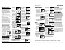
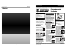
Guía de Diagnóstico de Averías
Deje de usar la clavadora inmediatamente si alguno de los si guientes problemas ocurre.
repuestos. Podría resultado le heridas graves. Cualquier reparación o reemplazo de piezas los
debe hacer un técnico calificado personal de un centro autorizado de servicio.
Problema Causa Solución
6-Sp
Manual de Instrucciones
Modelo RN164500
Recommended Hookup
Quick
Plug
Quick
Coupler
Air
Hose
Quick Plug
(Optional)
Quick
Coupler
(Optional)
Oiler
Regulator
Filter