


6
www.chpower.com
Operating Instructions and Parts Manual
WS4369 and WS4469
Operation
1. Be sure to read, understand, and
comply with all precautions in the
General Safety Information section.
Be sure to read the entire section
entitled Welding Guidelines prior to
using this equipment.
2. Turn welder off and plug into
appropriate receptacle: 230V-50
Amp
3. Verify that the surfaces of metals
to be joined are free from dirt,
rust, paint, oil, scale or other
contaminants. These contaminants
make welding difficult and cause
poor welds.
All persons
operating this
equipment or in the area while
equipment is in use must wear
protective welding gear including: eye
protection with proper shade (minimum
shade 10), flame resistant clothing,
leather welding gloves, and full foot
protection.
If heating, welding,
or cutting materials
that are galvanized, zinc plated,
lead, or cadmium plated refer to the
General Safety Information Section for
instructions. Extremely toxic fumes are
created when these metals are heated.
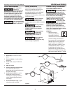
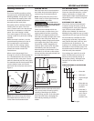
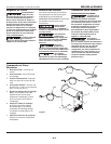
4. Connect the ground clamp to the
work piece or workbench (if metal).
Make sure the contact is secure, and
not obstructed by paint, varnish,
corrosion, or non-metallic materials.
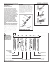
5. Insert the exposed part of the
electrode (the end with no flux)
into the jaws of the electrode
holder.
6. Set the amperage adjustment
knob to the proper amperage for
the electrode diameter. Refer to
the following chart for proper
electrode current settings.
The electrode
holder and rod
are electrically "hot"(have current
potential) when the welder is on.
Grounding against any metallic surface
may produce an arc which could cause
sparks and damage eyesight.
7. Hold the electrode and holder away
from the grounded work piece or
workbench. Turn on the welder.
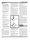
8. Position the electrode to begin
weld, lower the welding helmet or
position the hand shield, and strike
an arc. Adjust weld amperage as
needed.
9. When finished welding, turn
welder off and store properly.
DUTY CYCLE / THERMOSTATIC
PROTECTION
Welder duty cycle is the percentage of
actual weld time that can occur in a ten
minute interval. For example, at a 20%
duty cycle, actual welding can occur for
two minutes, then the welder must cool
for eight minutes.
Internal components of this welder are
protected from overheating with an
automatic thermal switch. A yellow
lamp is illuminated on the control panel
if the duty cycle is exceeded. Welding
operations may continue when the
yellow lamp is no longer illuminated.
Installation
LOCATION
Selecting the proper location can
significantly increase performance,
reliability and life of the arc welder.
• For best results locate the welder
in an environment that is clean and
dry. Avoid locations exposed to high
temperature, high humidity, dust
and corrosive fumes. High humidity
causes moisture condensation on
electrical components. Moisture can
contribute to corrosion and short
electrical components. Dust and dirt
in the welder retain moisture and
increase wear of moving parts.
• Place the welder in an area that
provides at least twelve inches
(305 mm) of ventilation space at
both the front and rear of the unit.
Keep all obstructions away from
this ventilation space.
• Store electrodes in a clean, dry
location with low humidity to
preserve the flux coating.
• The welder control panel contains
information regarding proper input
voltage and amperage. Follow the
specifications on the welder front
panel.
• The receptacle used for the welder
must be properly grounded and
the welder must be the only load
on the power supply circuit. Refer
to the Circuit Amps chart under
Specifications for correct circuit
capacity.
• The use of an extension cord is
not recommended for electric arc
welding machines. The voltage
drop in the extension cord
may significantly degrade the
performance of the welder.
Electrode
Diameter
Current Setting
(Amps)
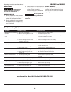
3/32 inch (2.5 mm) 60-110
1/8 inch (3.2 mm) 110-160
5/32 inch (4.0 mm) 150-230