


Set-Up (Cont.)
HOSES
Examine the hoses
carefully before
each use. If cuts, burns, worn areas or
damaged fittings are found, replace the
hose.
Perform the following procedure to
clear preservative talc if using a new
hose for the first time:
1. Connect the hose to the regulators.
Tighten connections securely with
wrench.
2. Turn regulator adjusting knobs
counter-clockwise to disengage
regulator (no-flow).
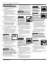
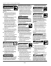
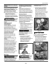
3. Slowly open the oxygen cylinder
valve until it is completely open.
!
CAUTION
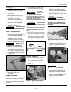
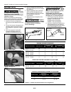
4. Slowly open the fuel cylinder valve
not more than one full turn (see
Figure 4).
5. Adjust the oxygen regulator to allow
3-5 PSI to escape through the hose.
Allow oxygen to flow 3-5 seconds to
clear hose of preservative.
6. Clear the acetylene hose in the same
manner.
Always clear
hoses in a well
ventilated area away from any flames
or other source of ignition.
!
CAUTION
4
Portable Oxy-Fuel Welding and Cutting Outfit
SELECTING THE PROPER
ATTACHMENT
Do NOT use the
torch handle if
grease, oil or other flammable
substances or damage are present!
Have a qualified technician clean the
torch or repair damage.
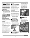
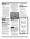
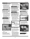
1. Attach fuel gas hose (red) to torch
valve marked “Fuel” and the Oxygen
(green) hose to valve marked “Oxy”
(see Figure 6).
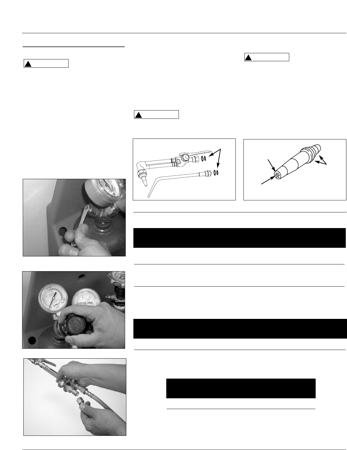
2. Inspect torch handle and all
apparatus for dust, dirt, grease, oil,
!
WARNING
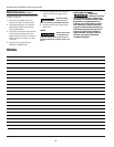
Oxygen Pressure Acetylene Pressure
Metal Thickness Tip Size P.S.I.G. P.S.I.G.
Min. Max Min Max
1/64” - 1/32” 00 3 5 3 5
1/32” - 5/64” 0 3 5 3 5
1/16” - 3/32” 1 3 5 3 5
3/32” - 1/8” 2 3 5 3 5
1/8” - 3/16” 3 4 7 3 6
3/16” - 1/4” 4 5 10 4 7
1/4” - 5/16” 5 6 12 5 8
Acetylene Oxygen
Tip Size Pressure Range Pressure Range
P.S.I.G. P.S.I.G.
6 4 - 6 8 - 11
8 8 - 12 10 - 18
1/4” - 1/2” 0 30 35 3 5
3/8” - 3/4” 1 30 35 3 5
Oxygen Pressure Acetylene Pressure
Metal Thickness Nozzle P.S.I.G. P.S.I.G.
Size Min. Max Min Max
OXY-ACETYLENE CUTTING NOZZLE CHART
WELDING TIP CHART
OXY-ACETYLENE MULTI-FLAME HEATING TIPS
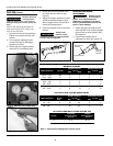
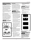
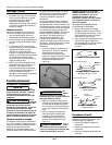
Figure 7 - Checking O-Rings
Figure 8 - Cutting Tip
Preheat Gas
Orifices
Oxygen Orifice
Tapered
Seating
Surfaces
Table 1 - Tip Selection and Regulator Pressure Charts
O-rings
www.chpower.com
Figure 4 - Turning on gas
Figure 5 - Adjusting fuel cylinder valve
Figure 6 - Attaching hoses