


5
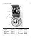
Model WT5000
1. Turn regulator adjusting knob
counter-clockwise to disengage
regulator (no-flow).
Never open
cylinder valve
with regulator adjusting knob
engaged. This condition can allow high
pressure gas to damage the internal
parts of the regulator, which can result
in explosion, fire or damage to
equipment, personal injury or property
damage.
Stand to the side
of the cylinder
opposite the regulator when opening
the cylinder valve. Keep the cylinder
valve between you and the regulator.
NEVER stand in front of or behind a
regulator when opening the cylinder
valve.
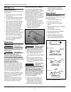
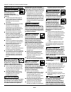
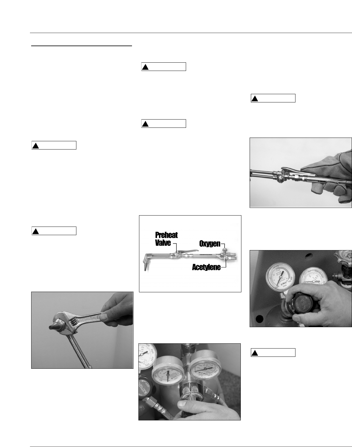
2. Close both torch handle valves. If
using the cutting attachment, open
the oxygen torch handle valve
completely and close the preheat
valve on the cutting attachment
(see Figure 10).
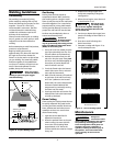
3. Slowly open the oxygen cylinder
valve until it is completely open.
Turn oxygen pressure adjusting
knob clockwise and set to 5 PSI (see
Figure 11).
!
WARNING
!
WARNING
4. Open the torch oxygen valve and
preheat valve, depress the cutting
lever if used and adjust regulator to
proper outlet pressure for welding
application (see Table 1). Close torch
or preheat valve after purging (see
Figure 10).
Do NOT open
acetylene cylinder
valve more than one (1) turn. Keep the
cylinder valve wrench, if one is
required, on the cylinder valve so that
the cylinder may be turned off quickly,
if necessary.
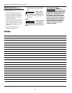
5. Slowly open the fuel cylinder valve
not more than one full turn, then set
regulator to 5 PSI with torch valve
closed (see Figure 13).
Never exceed
15 PSI output
pressure with acetylene.
6. Open fuel torch valve and allow gas
to flow about two seconds for each
ten feet of hose. Adjust regulator
pressure for welding application (See
Table 1). Close torch valve after
purging.
!
WARNING
!
WARNING
Set-Up
(Cont.)
other flammable substances or
damaged parts. Have a qualified
technician clean handle or repair
any damage.
3. Select the proper size and type of
welding tip (See Table 1). Inspect
the welding tip or cutting
attachment for missing O-rings.
Connect welding tip or cutting
attachment to torch handle by
hand-tightening the O-ring
connection (see Figure 7).
There must be two
(2) O-rings on the
cone end. The absence of either O-ring
can lead to flashback within the torch
handle or cutting attachment.
4. For cutting attachment, inspect the
tapered seating surfaces on tip and
in torch head. Have a qualified
technician resurface the seat area if
it has dents, burrs or is burned. A
poor seating surface may result in
backfire or flashback (see Figure 8).
Do NOT use a tip
or torch head that
has damage on the tapered seats.
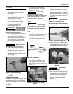
5. Inspect the cutting or welding tip
opening. Spatter can stick on or in
this opening. Remove spatter with
the tip cleaner. Tighten cutting tip
to torch head securely with wrench
(see Figure 9).
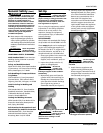
6. Purge system and check
connections.
PURGING THE SYSTEM
Purge only in a well ventilated area. Do
not direct flow of any gas towards any
person or flammable materials. Do not
purge near open flames or any source
of ignition.
!
WARNING
!
WARNING
www.chpower.com
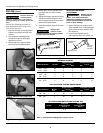
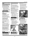
Figure 9 - Tightening cutting tip
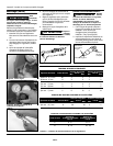
Figure 10 - Torch Handle
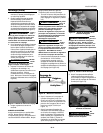
Figure 11 - Adjusting oxygen cylinder
regulator
Figure 12 - Pressing on cutting lever
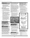
Figure 13 - Adjusting fuel cylinder
regulator