


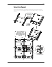
Setup
Dipswitch Settings
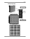
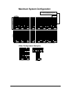
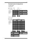
A DV-Wall video display matrix may consist of up to 16 drivers or 16 individual grid sections in various
pattern configurations. Each driver must be addressed according to your configuration so that the
video displayed appears whole and intact. Two internal dipswitches (JP1 & JP2) are addressed
according to your system layout and configuration.
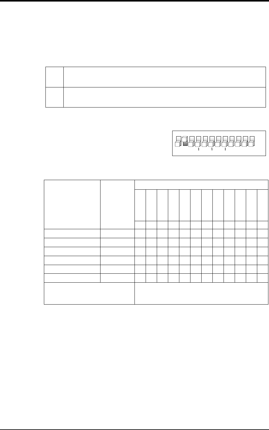
JP1
Sets the total width one driver will display. The width can be described in either number
of panels or pixel resolution. Possible widths include 1 to 6 panels or 16 to 96 horizontal
pixels.
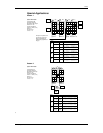
JP2
Sets the starting vertical line from which this driver will begin to display video. Remember
that a matrix may consist of multiple sections across, so in order to display video
correctly you will need to set the starting address for each section handled by a driver.
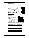
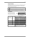
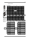
JP1 Dipswitch
JP1 dipswitches have their own unique
addressing method. For example setting
dipswitch 3 to ON adds 32 values to the
counter while setting 11 to ON subtracts 16.
1
2
3
4
5
6 7 8 9 10
11
12
ON
OFF
W32
W64
W128
W256
W512
W1024
-W16
JP1
DEFAULT SETTING = 32
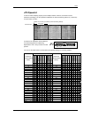
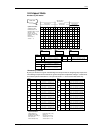
You can use the table below to quickly identify the dipswitch settings for your matrix width.
JP1 Dipswitches
(Default Off)
(Default On)
add 32
add 64
add 128
add 256
add 512
add 1024
(Default Off)
(Default Off)
subtract 16
(Default Off)
Horizontal Width in
(pixel columns or vertical
lines)
Number of
panels
1 2 3 4 5 6 7 8 9 10 11 12
16 1 1 1
32 2 1
48 3 1 1 1
64 4 1 1
80 5 1 1 1
96 6 1 1
Note: 1 = Dipswitch ON, Blank = Dipswitch OFF
The default setting of dipswitch # 2 ON and all others OFF
equals 32.
DV Wall System User Manual 13 2007-02-05/16:45