


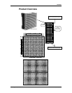
Setup
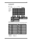
Transmitter Card
Install the transmitter card in an available PCI slot in your computer. The transmitter card is the
interface between your PC, DV-Wall Studio software and the DV-Wall Screen. You must use the DVI
cable provided to connect from the computers DVI output to the DVI port on the transmitter card.
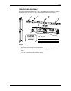
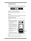
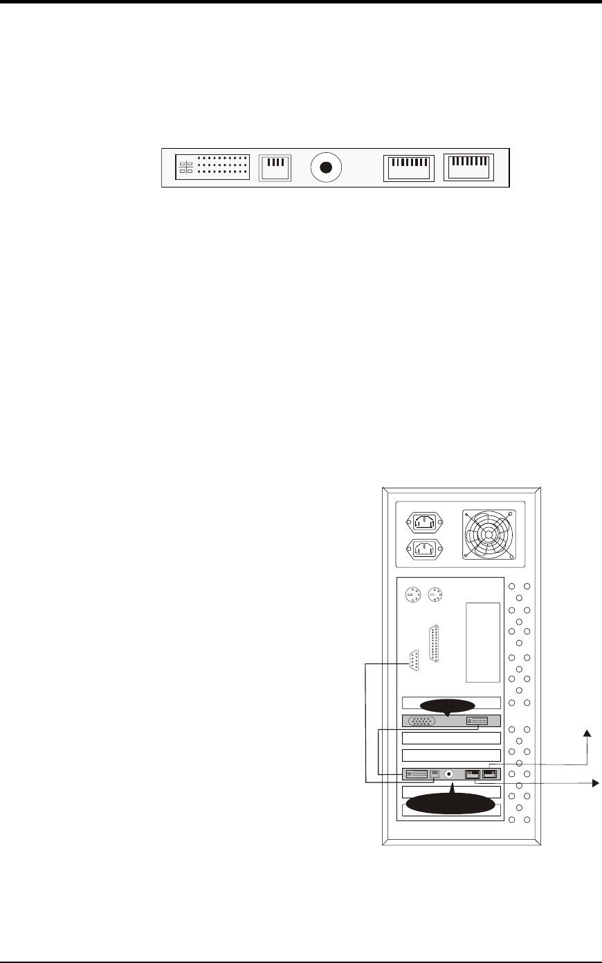
RJ- 45 RJ- 45
Aux portDVI Port
DC external
power input
Data Out 2 Data Out 1
Data Out 1 & Data Out 2 connectors
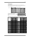
The two network output ports transmit 256 rows or horizontal lines. Output 1 transmits rows/lines 1
through 256. Output 2 transmits rows/lines 257 through 512.
Aux Port
This is a standard 6-pin telephone connector. A cable is provided that connects from the 9-pin DIN
RS232 port to the Aux port on the transmitter card. This port allows control of the R variable, gray
scale, DV Wall matrix active area, and matrix lock and matrix range.
DC External Power Input
This input takes a 5V power supply. It is only used if the transmitter card will be operated eternally of
the computer.
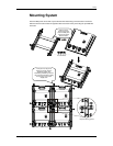
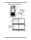
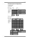
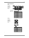
Transmitter Card Installation
RJ - 45
VGA DVI
COM
OUT1
OUT 2DVI
RJ - 45
1~256ROW
257~512ROW
DVI SIGNALCABLE
DISPLAYCARD
TRANSMITTER
RS232 SIGNALCABLE
NETCABLE
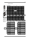
1. Turn off the computer before opening its case and
adding or removing components.
2. Insert the transmitter card into an available PCI
slot in your computer.
3. Connect out of your computer’s display card DVI
output and into the DVI input on the transmitter
card using the DVI signal cable provided.
4. Connect out of the serial RS232 (also COM port)
connector and into the 6-pin telephone connector
on the transmitter card using the RS232 signal
cable provided.
5. Plug the provided ethernet cable into the
RJ45 connector labeled OUT 1 and into a
driver’s etherbet IN connector to display rows
1 through 256.
6. If using displaying 512 row lines connect the
OUT 2 as well to a new driver.
7. Secure all connections.
8. In order to test the system successfully it will be
necessary to address the drivers correctly. Jump
to the section in this manual on driver dipswitch
settings.
9. Once drivers are assigned, turn on the computer and test the system.
Note!
If your computer reboots or turns off abruptly; please remove the DVI cable from the transmitter card
and reboot your computer. After Windows loads reconnect the DVI cable.
DV Wall System User Manual 15 2007-02-05/16:45