


Table of Contents Table of Contents
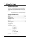
1. BEFORE YOU BEGIN....................................................................................................................................................... 3
UNPACKING INSTRUCTIONS..............................................................................................................................................................................................3
CONTACT US...................................................................................................................................................................................................................3
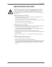
IMPORTANT SAFETY INFORMATION................................................................................................................................................................................... 4
2. INTRODUCTION ............................................................................................................................................................... 5
OVERVIEW ......................................................................................................................................................................................................................5
FEATURES.......................................................................................................................................................................................................................5
COMPUTER SYSTEM REQUIREMENTS...............................................................................................................................................................................5
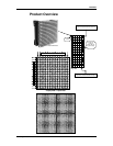
PRODUCT OVERVIEW....................................................................................................................................................................................................... 6
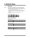
3. HARDWARE SETUP......................................................................................................................................................... 7
AC POWER ..................................................................................................................................................................................................................... 7
SYSTEM LIMITATIONS....................................................................................................................................................................................................... 7
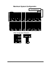
MAXIMUM SYSTEM CONFIGURATION ................................................................................................................................................................................8
Other Configuration Examples.................................................................................................................................................................................8
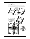
MOUNTING SYSTEM.........................................................................................................................................................................................................9
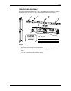
Flying bracket attachment......................................................................................................................................................................................10
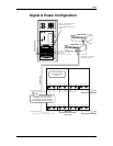
SIGNAL & POWER CONFIGURATION................................................................................................................................................................................11
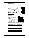
DV-WALL DRIVER .........................................................................................................................................................................................................12
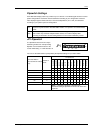
Dipswitch Settings..................................................................................................................................................................................................13
JP1 Dipswitch.........................................................................................................................................................................................................13
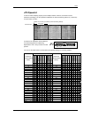
JP2 Dipswitch.........................................................................................................................................................................................................14
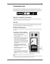
TRANSMITTER CARD......................................................................................................................................................................................................15
Data Out 1 & Data Out 2 connectors.....................................................................................................................................................................15
Aux Port .................................................................................................................................................................................................................15
DC External Power Input.......................................................................................................................................................................................15
Transmitter Card Installation..................................................................................................................................................................................15
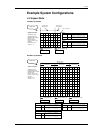
EXAMPLE SYSTEM CONFIGURATIONS.............................................................................................................................................................................16
4:3 Aspect Ratio.....................................................................................................................................................................................................16
4 meters by 3 meter .........................................................................................................................................................................................16
8 meters by 6 meters........................................................................................................................................................................................16
16 meters by 12 meters....................................................................................................................................................................................17
16:9 Aspect Ratio...................................................................................................................................................................................................18
8 meters by 4.5 meters.....................................................................................................................................................................................18
16 meters by 9 meters......................................................................................................................................................................................18
Special Applications...............................................................................................................................................................................................19
Pattern 1...........................................................................................................................................................................................................19
Pattern 2...........................................................................................................................................................................................................19
4. APPENDIX....................................................................................................................................................................... 20
RETURNS PROCEDURE..................................................................................................................................................................................................20
CLAIMS .........................................................................................................................................................................................................................20
MAINTENANCE...............................................................................................................................................................................................................20
TECHNICAL SPECIFICATIONS (PER PANEL)......................................................................................................................................................................21
TECHNICAL SUPPORT ....................................................................................................................................................................................................21
©CHAUVET, 2006, All Rights Reserved
Information and specifications in this User Manual are subject to change without
notice. CHAUVET assumes no responsibility or liability for any errors or
inaccuracies that may appear in this manual.
DV Wall System User Manual 2 2007-02-05
/16:45