


Setup
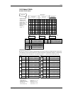
JP2 Dipswitch
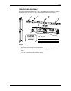
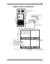
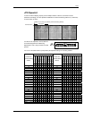
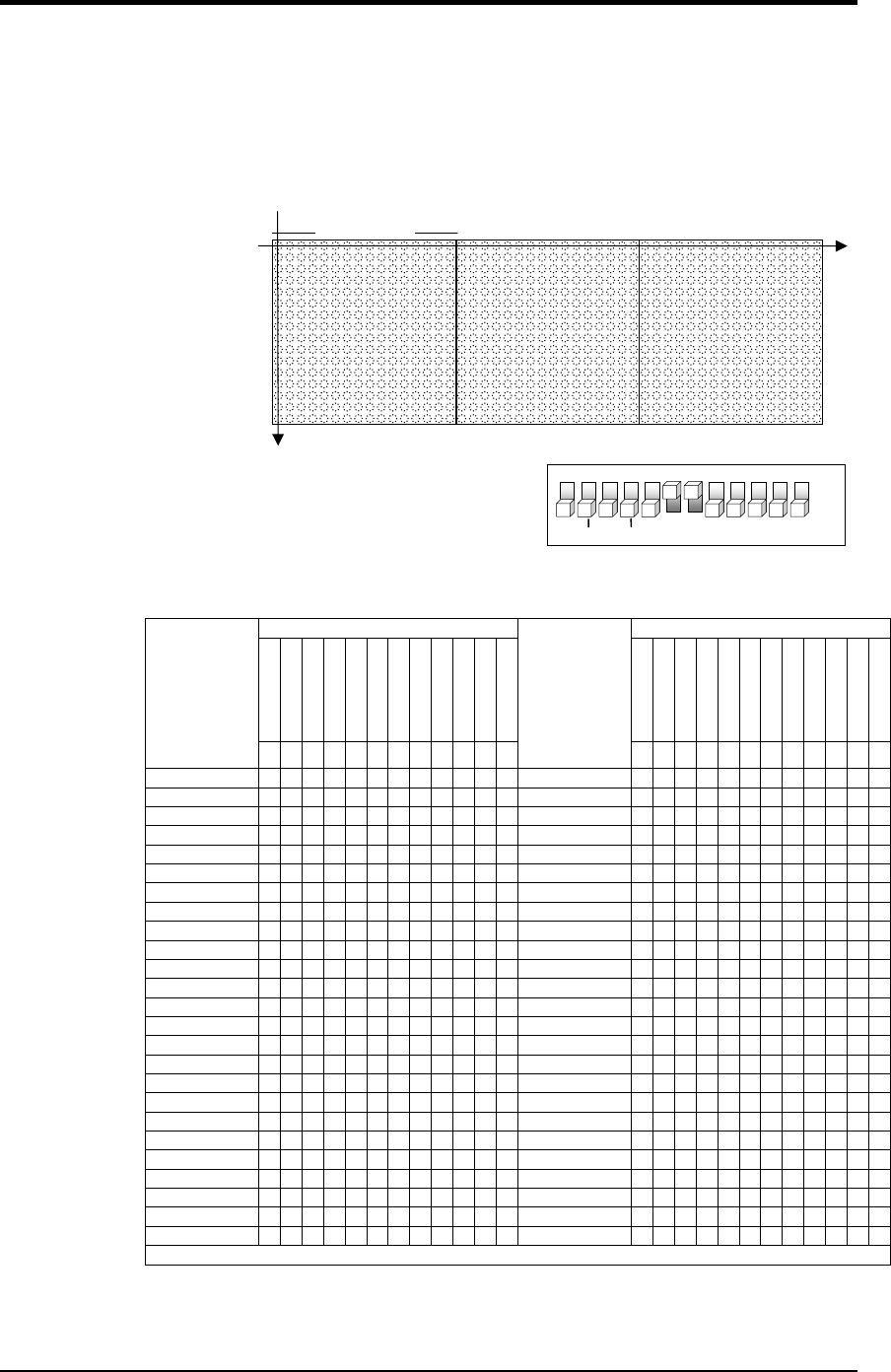
In order for video to display properly across multiple sections or drivers, each driver must be
addressed accordingly. The JP2 dipswitch establishes the horizontal starting address or (vertical line)
for each section of matrix.
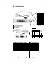
Horizontal Line
16 lines/
p
ixels
Vertical Line, JP2 set @ 0 (default) (horizontal starting address)
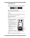
Just like the JP1 dipswitch, JP2 has different
numerical designations for addressing.
Dipswitches 6 and 7 always remain in the ON
position.
1
2
3
4
5
6 7 8 9 10
11
12
ON
OFF
S64
S128
S256
S512
S32 S16
JP2
DEFAULT START ADDR = 0
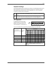
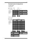
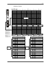
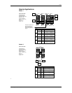
You can use the table below to quickly identify the dipswitch settings for a starting address.
JP2 Dipswitches JP2 Dipswitches
add 64
add 128
add 256
add 512
(Default Off)
(Default On)
(Default On)
(Default Off)
(Default Off)
(Default Off)
add 16
add 32
add 64
add 128
add 256
add 512
(Default Off)
(Default On)
(Default On)
(Default Off)
(Default Off)
(Default Off)
add 16
add 32
Vertical Lines
(Horizontal starting
address)
1 2 3
4
5
6
7
8
9
10
11
12
Vertical Lines
(Horizontal starting
address)
1
2
3 4 5 6 7 8
9
10
11
12
0 1
1
400 1
1 1 1 1
16 1
1
1
416 1
1 1 1 1
32 1
1
1
432 1
1 1 1 1
1
48 1
1
1
1
448 1
1
1 1 1
64 1 1
1
464 1
1
1 1 1 1
80 1 1
1
1
480 1
1
1 1 1 1
96 1 1
1
1
496 1
1
1 1 1 1
1
112 1 1
1
1
1
512 1 1 1
128 1 1
1
528 1 1 1 1
144 1 1
1
1
544 1 1 1 1
160 1 1
1
1
560 1 1 1 1
1
176 1 1
1
1
1
576 1
1 1 1
192 1 1 1
1
592 1
1 1 1 1
208 1 1 1
1
1
608 1
1 1 1 1
224 1 1 1
1
1
624 1
1 1 1 1
1
240 1 1 1
1
1
1
640 1
1 1 1
256 1
1
1
656 1
1 1 1 1
272 1
1
1
1
672 1
1 1 1 1
288 1
1
1
1
688 1
1 1 1 1
1
304 1
1
1
1
1
704 1
1
1 1 1
320 1 1
1
1
720 1
1
1 1 1 1
336 1 1
1
1
1
736 1
1
1 1 1 1
352 1 1
1
1
1
752 1
1
1 1 1 1
1
368 1 1
1
1
1
1
768 1 1 1 1
384 1 1
1
1
Note: 1 = Dipswitch ON, Blank = Dipswitch OFF
DV Wall System User Manual 14 2007-02-05/16:45